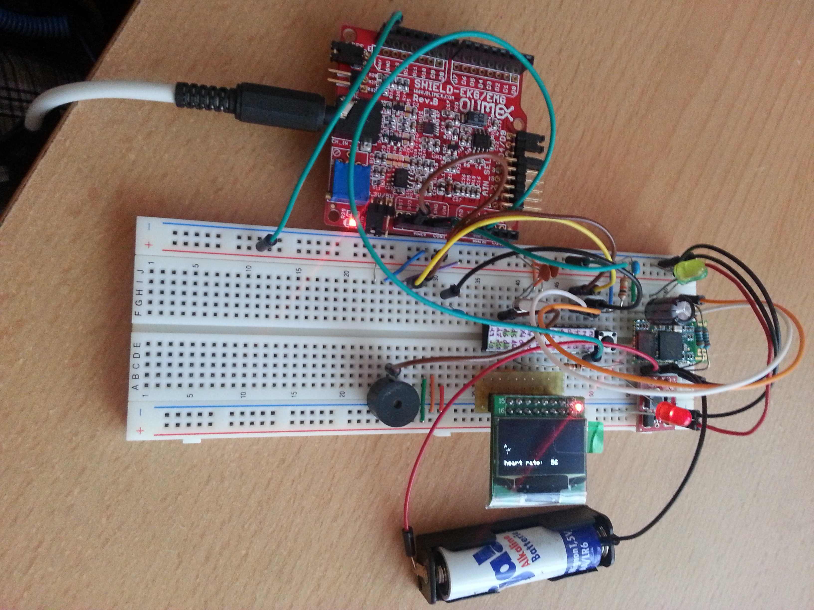
This experimental setup is a combination of the the 3.3V OLED display setup and the EKG/EMG shield with improved code, which does averaging of 4 RR intervals in order to calculate the heart rate. Also an annoying QRS-beep is added 🙂
//Simple Arduino ECG monitor with SSD1306 OLED display
//Incorporates a simple QRS detection algorithm and heart rate calculation
//the interrupt-based code parts are based on the Olimex approach
//Requires the libraries included below!
#include <Wire.h>
#include <Adafruit_GFX.h>
#include <Adafruit_SSD1306.h>
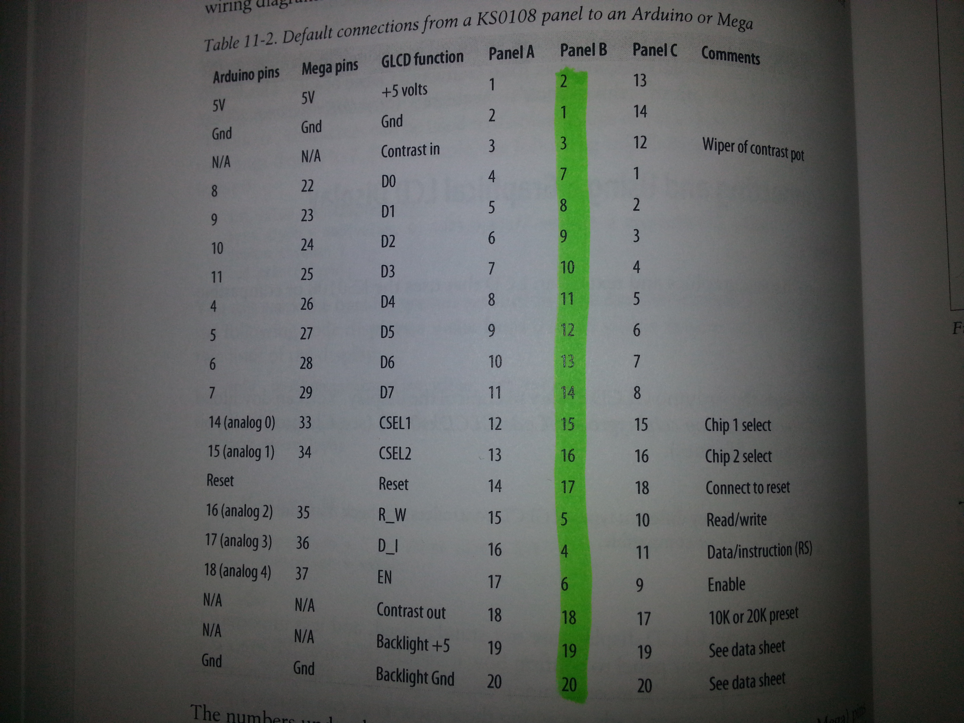
//connect the OLED display in the following way:
#define OLED_DC 11
#define OLED_CS 12
#define OLED_CLK 10
#define OLED_MOSI 9
#define OLED_RESET 13
Adafruit_SSD1306 display(OLED_MOSI, OLED_CLK, OLED_DC, OLED_RESET, OLED_CS);
#if (SSD1306_LCDHEIGHT != 64)
#error("Height incorrect, please fix Adafruit_SSD1306.h!");
#endif
#include <compat/deprecated.h>
#include <FlexiTimer2.h>
//http://www.arduino.cc/playground/Main/FlexiTimer2
#include <TimerOne.h>
//http://arduino.cc/playground/Code/Timer1
/*
Erklärung von cbi, sbi, outp und inp
Bei solchen Makros sollte man etwas mehr Klammern spendieren:
#define sbi(ADDRESS,BIT) ((ADDRESS) |= (1<<(BIT)))
#define cbi(ADDRESS,BIT) ((ADDRESS) &= ~(1<<(BIT)))
#define outp(VAL,ADRESS) ((ADRESS) = (VAL))
#define inp(VAL) (VAL)
The outb( ) function provides a C language interface to the machine instruction that writes a byte to an 8 bit I/O port using the I/O address space instead of the memory address space.
*/
// All definitions
#define NUMCHANNELS 6
#define HEADERLEN 4
#define PACKETLEN (NUMCHANNELS * 2 + HEADERLEN + 1) //6*2+4+1
#define SAMPFREQ 256 // ADC sampling rate 256
#define TIMER2VAL (1024/(SAMPFREQ)) // Set 256Hz sampling frequency
#define PWM_OUT 9 // Number of pin used for generating CAL_SIG
#define PWMFREQ 10 //10Hz for Calibration signal
//#define LED1 13
// Global constants and variables
char const channel_order[]= { 0, 1, 2, 3, 4, 5 };
volatile unsigned char TXBuf[PACKETLEN]; //The transmission packet
volatile unsigned char TXIndex; //Next byte to write in the transmission packet.
volatile unsigned char CurrentCh; //Current channel being sampled.
//~~~~~~~~~~
// Functions
//~~~~~~~~~~
/****************************************************/
/* Function name: Toggle_LED1 */
/* Parameters */
/* Input : No */
/* Output : No */
/* Action: Switches-over LED1. */
/****************************************************/
//void Toggle_LED1(void){
//
// if((digitalRead(LED1))==HIGH){
// digitalWrite(LED1,LOW);
// }
// else{
// digitalWrite(LED1,HIGH);
// }
//}
/****************************************************/
/* Function name: setup */
/* Parameters */
/* Input : No */
/* Output : No */
/* Action: Initializes all peripherals */
/****************************************************/
void setup() {
noInterrupts(); // Disable all interrupts before initialization
// LED1
// pinMode(LED1, OUTPUT); //Setup LED1 direction
// digitalWrite(LED1,LOW); //Setup LED1 state
//Write packet header and footer
TXBuf[0] = 0xa5; //Sync 0
TXBuf[1] = 0x5a; //Sync 1
TXBuf[2] = 2; //Protocol version
TXBuf[3] = 0; //Packet counter
// ADC
// Timings for sampling of one 10-bit AD-value:
// XTAL = 16000000MHz
// prescaler > ((XTAL / 200kHz) = 80 =>
// prescaler = 128 (ADPS2 = 1, ADPS1 = 1, ADPS0 = 1)
// ADCYCLE = XTAL / prescaler = 125000Hz or 8 us/cycle
// 14 (single conversion) cycles = 112 us
// 26 (1st conversion) cycles = 208 us
outb(ADMUX, 0); //Select channel 0
outb(ADCSRA, ((1<<ADPS2) | (1<<ADPS1)| (1<<ADPS0))); //Prescaler = 128, free running mode = off, interrupts off.
sbi(ADCSRA, ADIF); //Reset any pending ADC interrupts
sbi(ADCSRA, ADEN); //Enable the ADC
// Serial Port
outb(UBRR0, 16); //Set speed to 57600 bps
outb(UCSR0B, (1<<TXEN0)); //Enable USART Transmitter.
// Timer1
// It's used for calibration signal generation: CAL_SIG via PWM.
// CAL_SIG is used like reference signal when setting-up SHIELD-EKG/EMG's channel gain
// During normal operation this signal is not required so it can be disabled with uncommenting te row below!
/*
pinMode(PWM_OUT, OUTPUT); //Set PWM_OUT direction
digitalWrite(PWM_OUT,LOW); //Set PWM_OUT state
Timer1.initialize((1000000/(PWMFREQ))); // initialize timer1, and set a 1/10 second period = 10Hz ->freq. of cal signal should be 10-14Hz (schematic)
Timer1.pwm(PWM_OUT, 512); // setup pwm on pin 9, 50% duty cycle
//Timer1.disablePwm(PWM_OUT); // Uncomment if CAL_SIG is not requiered
*/
// Timer2
// Timer2 is used for setting ADC sampling frequency.
/*****************************************************************
Methods of the FlexiTimer2 library:
FlexiTimer2::set(unsigned long units, double resolution, void (*f)())
this function sets a time on units time the resolution for the overflow. Each overflow, "f" will be called. "f" has to be declared void with no parameters.
E.g. units=1, resolution = 1.0/3000 will call f 3000 times per second, whereas it would be called only 1500 times per second when units=2.
FlexiTimer2::set(unsigned long ms, void (*f)())
this function sets a time on ms (1/1000th of a second) for the overflow. Each overflow, "f" will be called. "f" has to be declared void with no parameters.
Shorthand for calling the function above with resolution = 0.001.
FlexiTimer2::start()
enables the interrupt.
FlexiTimer2::stop()
disables the interrupt.
*******************************************************************/
FlexiTimer2::set(TIMER2VAL, Timer2_Overflow_ISR); //TIMER2VAL was (1024/(SAMPFREQ)) in ms =4, SAMPLEFREQ was 256
FlexiTimer2::start(); //enable the Interrupt....
// MCU sleep mode = idle.
outb(MCUCR,(inp(MCUCR) | (1<<SE)) & (~(1<<SM0) | ~(1<<SM1) | ~(1<<SM2)));
interrupts(); // Enable all interrupts after initialization has been completed
// by default, we'll generate the high voltage from the 3.3v line internally! (neat!)
display.begin(SSD1306_SWITCHCAPVCC);
// init done
display.clearDisplay(); // clears the screen and buffer
display.setTextSize(1);
display.setTextColor(WHITE);
}
/****************************************************/
/* Function name: Timer2_Overflow_ISR */
/* Parameters */
/* Input : No */
/* Output : No */
/* Action: Determines ADC sampling frequency. */
/****************************************************/
void Timer2_Overflow_ISR() //alle 4ms wird das ausgeführt
{
// Toggle LED1 with ADC sampling frequency /2
//Toggle_LED1();
CurrentCh = 0;
// Write header and footer:
// Increase packet counter (fourth byte in header)
//Write packet header and footer
/**********zur Erinnerung: der Header**********
TXBuf[0] = 0xa5; //Sync 0
TXBuf[1] = 0x5a; //Sync 1
TXBuf[2] = 2; //Protocol version
TXBuf[3] = 0; //Packet counter
***********************************/
TXBuf[3]++;
//the whole packet is /6*2+4+1=17byte
//Get state of switches on PD2..5, if any (last byte in packet).
TXBuf[2 * NUMCHANNELS + HEADERLEN] = (inp(PIND) >> 2) &0x0F; //2* NUMCHANNELS, weil jeder CHannel 2 byte hat damit 1024 reinpasst
cbi(UCSR0B, UDRIE0); //Ensure Data Register Empty Interrupt is disabled.
sbi(ADCSRA, ADIF); //Reset any pending ADC interrupts
sbi(ADCSRA, ADIE); //Enable ADC interrupts.
sbi(ADCSRA, ADSC) ; // Start conversion!!!
//Next interrupt will be ISR(ADC_vect)
}
/****************************************************/
/* Function name: ISR(ADC_vect) */
/* Parameters */
/* Input : No */
/* Output : No */
/* Action: Reads ADC's current selected channel */
/* and stores its value into TXBuf. When */
/* TXBuf is full, it starts sending. */
/****************************************************/
ISR(ADC_vect)
{
volatile unsigned char i; //volatile??
i = 2 * CurrentCh + HEADERLEN; //also wird i auf 4 gesetzt wenn CurrentCh==0 und unten das 5. byte beschrieben,danach TxBuf[4] ([3] ist das letzte vom Header)
TXBuf[i+1] = inp(ADCL); //ADC data register LOW byte
TXBuf[i] = inp(ADCH); //ADC data register HIGH byte
CurrentCh++;
if (CurrentCh < NUMCHANNELS)
{
outb(ADMUX, (channel_order[CurrentCh])); //Select the next channel.
sbi(ADCSRA, ADSC) ; //Start conversion!!! (set ADSC-bit in ADCSRA-Register)
}
else
{
//this gets executed first....prior to the stuff above
outb(ADMUX, channel_order[0]); //Prepare next conversion, on channel 0.
cbi(ADCSRA, ADIE); //Disable ADC interrupts to prevent further calls to ISR(ADC_vect). oben hiess es sbi!!!!!!
outb(UDR0, TXBuf[0]); //Send first Packet's byte: Sync 0
sbi(UCSR0B, UDRIE0); //USART Data Register Empty Interrupt Enable
TXIndex = 1; //Next interrupt will be ISR(USART_UDRE_vect)
}
}
/****************************************************/
/* Function name: ISR(USART_UDRE_vect) */
/* Parameters */
/* Input : No */
/* Output : No */
/* Action: Sends remaining part of the Packet. */
/****************************************************/
ISR(USART_UDRE_vect){
outb(UDR0, TXBuf[TXIndex]); //Send next byte
TXIndex++;
/******hier also***
ch0hb = TxBuf[4];
ch0lb = TxBuf[5];
*******************/
if (TXIndex == PACKETLEN) //See if we're done with this packet
{
cbi(UCSR0B, UDRIE0); //USART Data Register Empty Interrupt Disable
//Next interrupt will be Timer2_Overflow_ISR()
}
}
//function for fusion of the ADCL and ADCH byte
unsigned int weiterverarbeitung(volatile unsigned char high_byte, volatile unsigned char low_byte)
{
unsigned int value = ((high_byte&0x0f)*256)+(low_byte);
return(value);
}
/****************************************************/
/* Function name: loop */
/* Parameters */
/* Input : last 2 channel bytes of the packet */
/* Output : to display */
/* Action: Draws ECG, detects QRS, calculates HR */
/****************************************************/
unsigned long Start, Finished = 0;
int heart_rate[4];
int heart_rate_avg;
float RR_interval = 0.0;
unsigned int Delay = 2;
unsigned int QRS_counter = 0;
int thisdot = 0;
int prevdot = 0;
void loop() {
//"heart rate"
display.setCursor(1,52);
display.print("heart rate:");
display.display(); // show it
//show heart rate once per screen
if(heart_rate_avg<220)
{
display.setCursor(80,52);
display.print(heart_rate_avg);
display.display(); // show it
}
//draw the actual graph: (128 = display width)
for(int i=0; i<128; i++)
{
Finished = 0;
//get the ADC value and scale it to the higth of the display
unsigned int val = weiterverarbeitung(TXBuf[14],TXBuf[15]); //using A5 and extracting the last 2 channel bytes out of the packet
unsigned int y = map (val, 0, 1023, 64, 0); //oben=0!!
thisdot = y;
//calculate the graph slope for QRS detection
//slope can be negative so it has to be an SIGNED int
int slope = prevdot - thisdot;
//QRS complex detected above a certain threshold
if (slope >= 8 && Start == 0)
{
//QRS Beep, use Pin 6 to not interfere with Timer 2!!
tone(6, 2000, 50);
//start "stop watch"
Start = millis();
}
else if(slope >= 8 && Start > 0)
{
//QRS Beep
tone(6, 2000, 50);
//stop
Finished = millis();
//calculate a RR interval
RR_interval = Finished - Start;
if(RR_interval>=150) //refractory period, RR-intervals should be longer than this (filter method)
{
RR_interval = RR_interval/1000; //convert to seconds
heart_rate[QRS_counter] = 60/RR_interval; //collect 4 intervals
QRS_counter ++;
//averaging calculation
if(QRS_counter >= 3){
for(int j = 0; j<4; j++){
heart_rate_avg += heart_rate[j];
}
heart_rate_avg /= 4;
QRS_counter = 0;
}
}
//reset Start value for time measurement
Start = 0;
}
//Draw graph
display.drawPixel(i, y, WHITE);
display.display();
delay(Delay);
prevdot = thisdot;
thisdot = 0;
slope = 0;
}
display.clearDisplay();
}