Category Archives: Misc Electronics

Analog circuits and other electronics-related hacks and projects.

Semi-Automatic Spot Welder

Sometimes I feel the need for a spot welder for welding battery tabs. Since soldering batteries can damage their chemistry and commercial spot welders are too expensive, I decided to build my own from scrap. I don’t recommend doing this if you are not confident with electrical stuff since this project ivolves mains voltage and high currents which result in an overall power of around 1000W! You have been warned!


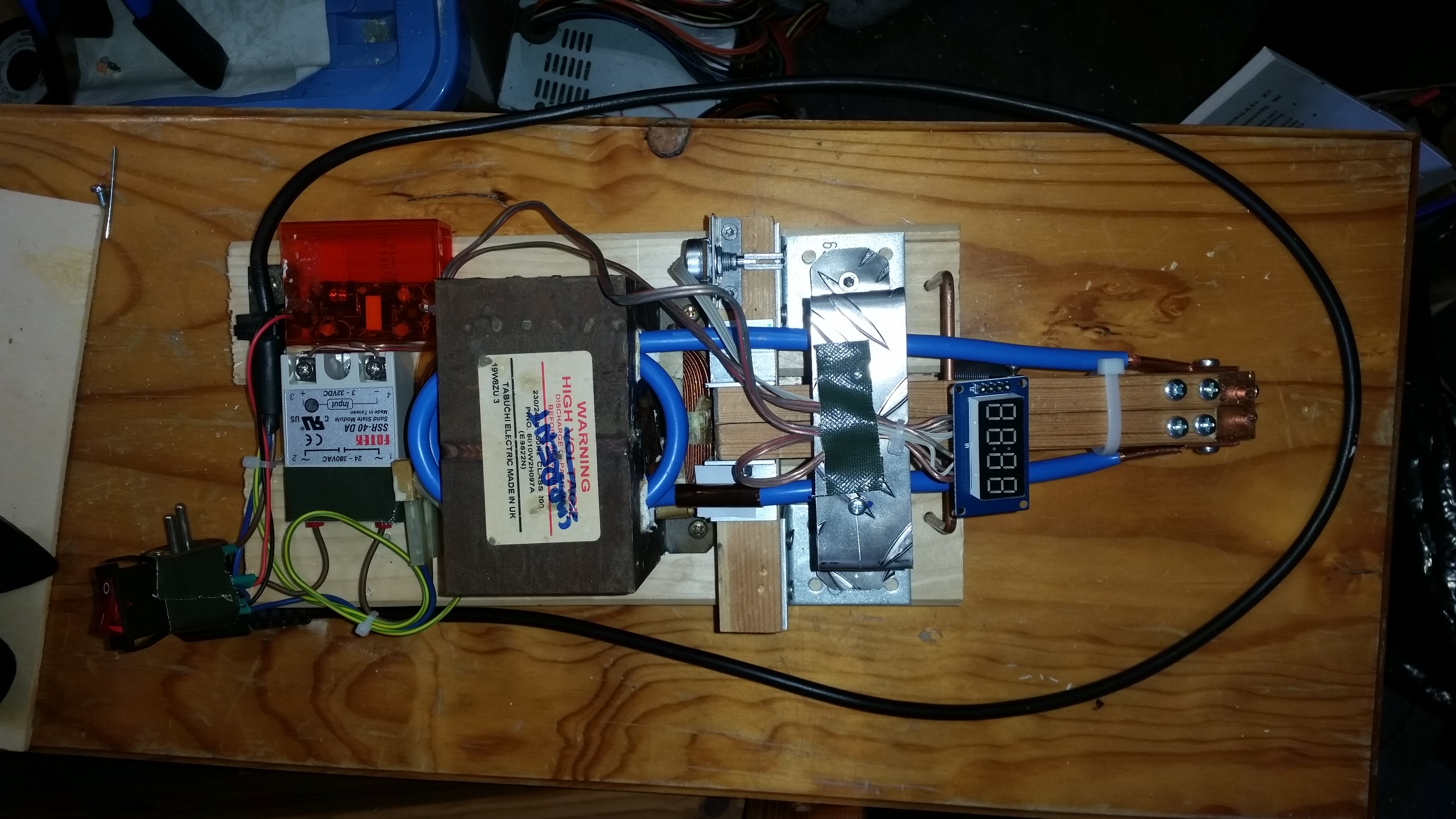
Microwave oven transformers (MOTs) can be obtained for free and have great potential to be used or abused in various projects. One popular use of MOTs is in DIY spot welders. One has to remove the secondary (high voltage) winding and sqeeze in 2-3 turns of heavy gauge copper wire in order to get 1.5-3V @ ca. 400A. There is an infinite amount of information on how to do this online so I won’t cover it too deeply.
I was able to squeeze 2.5 turns onto the core using ca. 8mm thick stranded copper wire. The electrode blocks are made from pure copper (12x12x50mm copper bars) to minimize resistance and sink the heat. The lugs that connect the wire to the blocks can be made from copper sheets or copper pipe. The welding electrodes are 4.5mm solid copper wire with pointed tips. I had to experiment a little with electrode distance and tip geometry. 3-10mm distance and round tip geometry are probably good starting points.


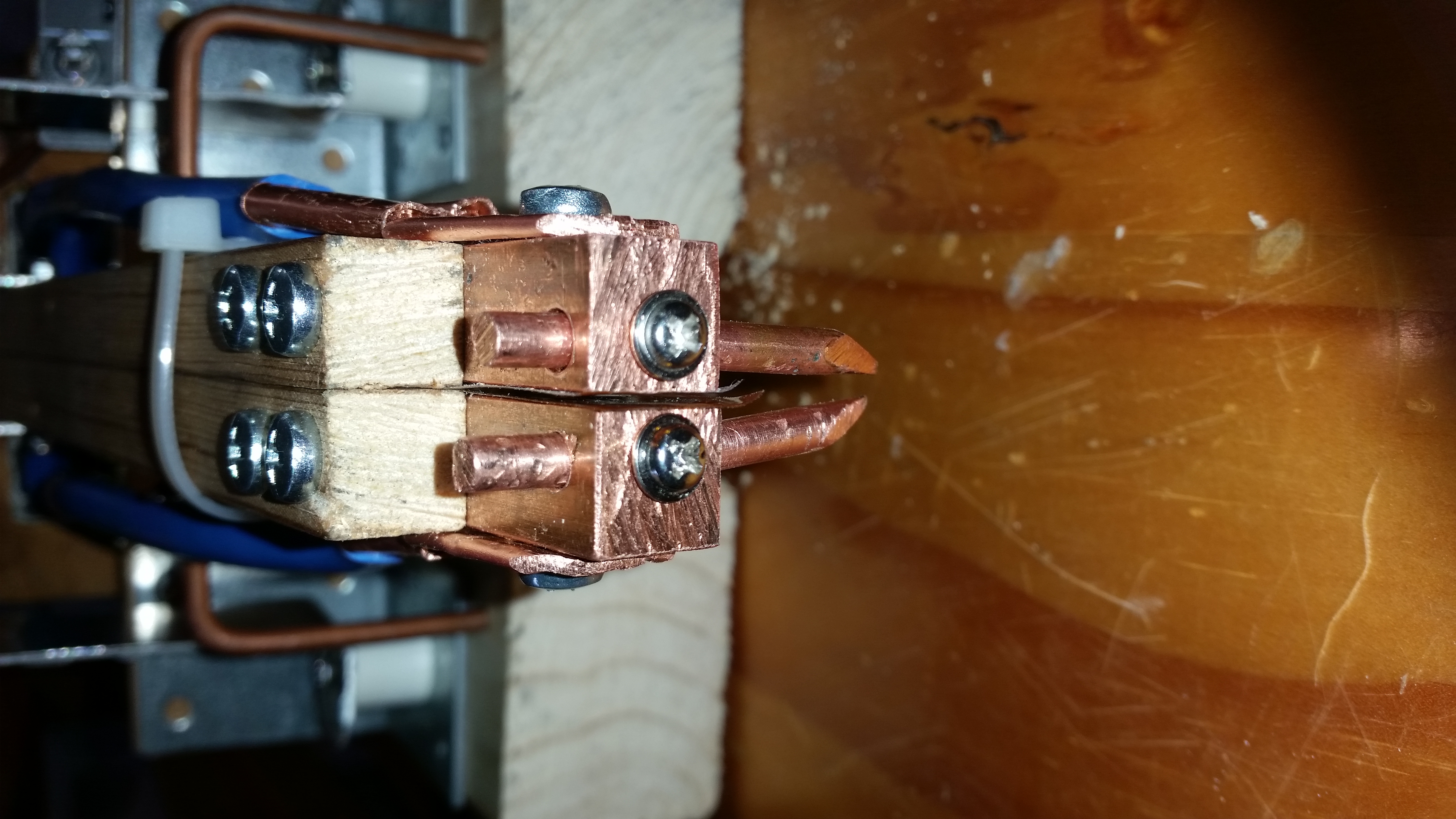
In order to get consistent welds, some parameters have to be controlled with the most important being mechanical force of the electrode to the workpiece and duration of the high current pulse. The idea behind resistance spot welding is that the spots where electrodes touch the workpiece are the areas of highest electrical resistance and therefore they heat up, melt and fuse together. My welder is built in a “series configuration” which means that both electrodes are at the top as opposed to the alternative variant where one is at the top end the other at the bottom. It is important for both welding electrodes to have near-equal mechanical force on the workpiece and therefore both are spring-loaded individually. Two microswitches in series ensure that the same force on every electrode is applied every time. Only when both microswitches are triggered, the welding pulse is applied. Afterwards the system waits for some seconds until the next weld can be performed. Note that the cable tie on the pictures only holds both arms together losely. They are still able to move away from each other for at least 10mm which is sufficient.


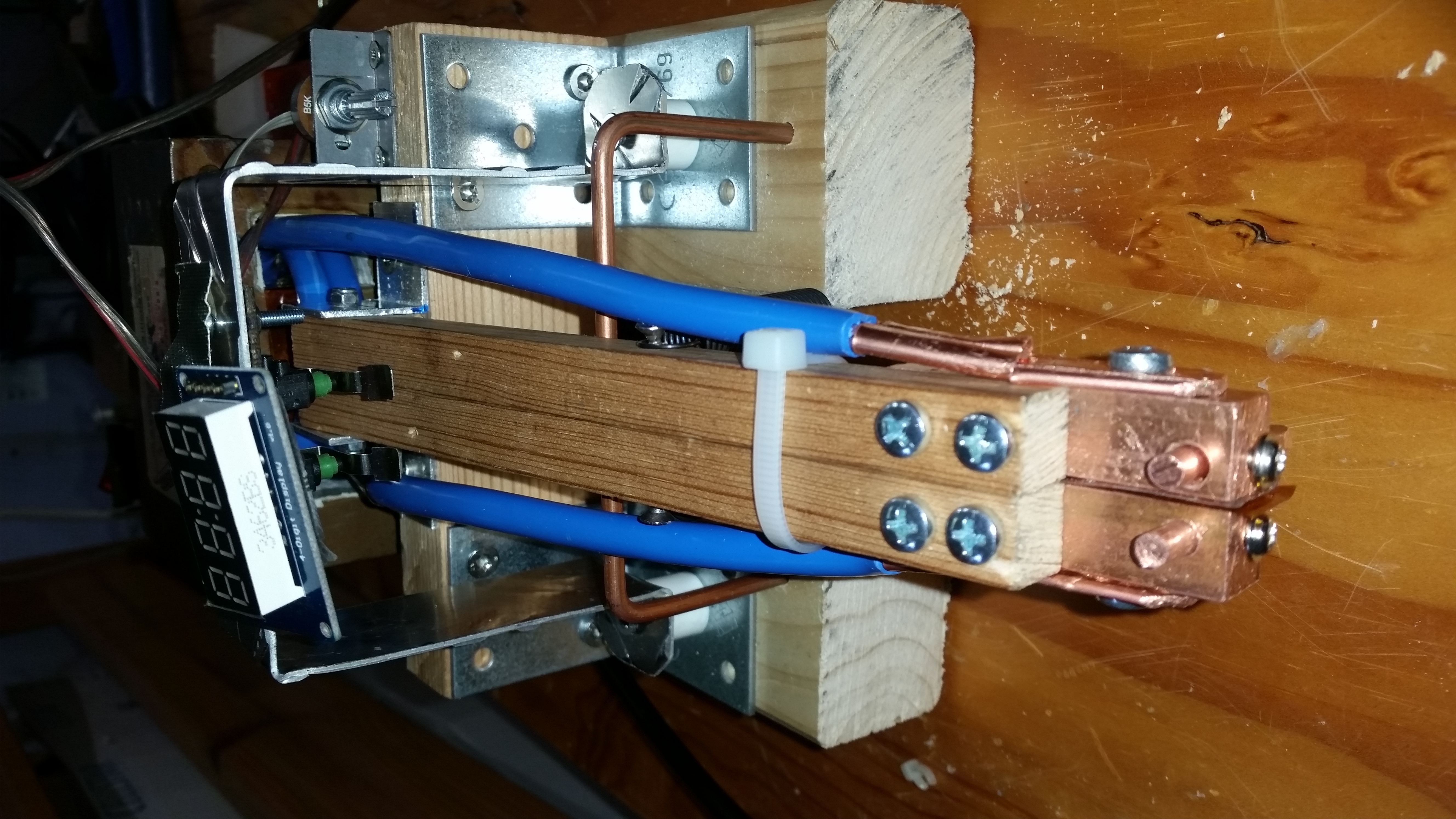
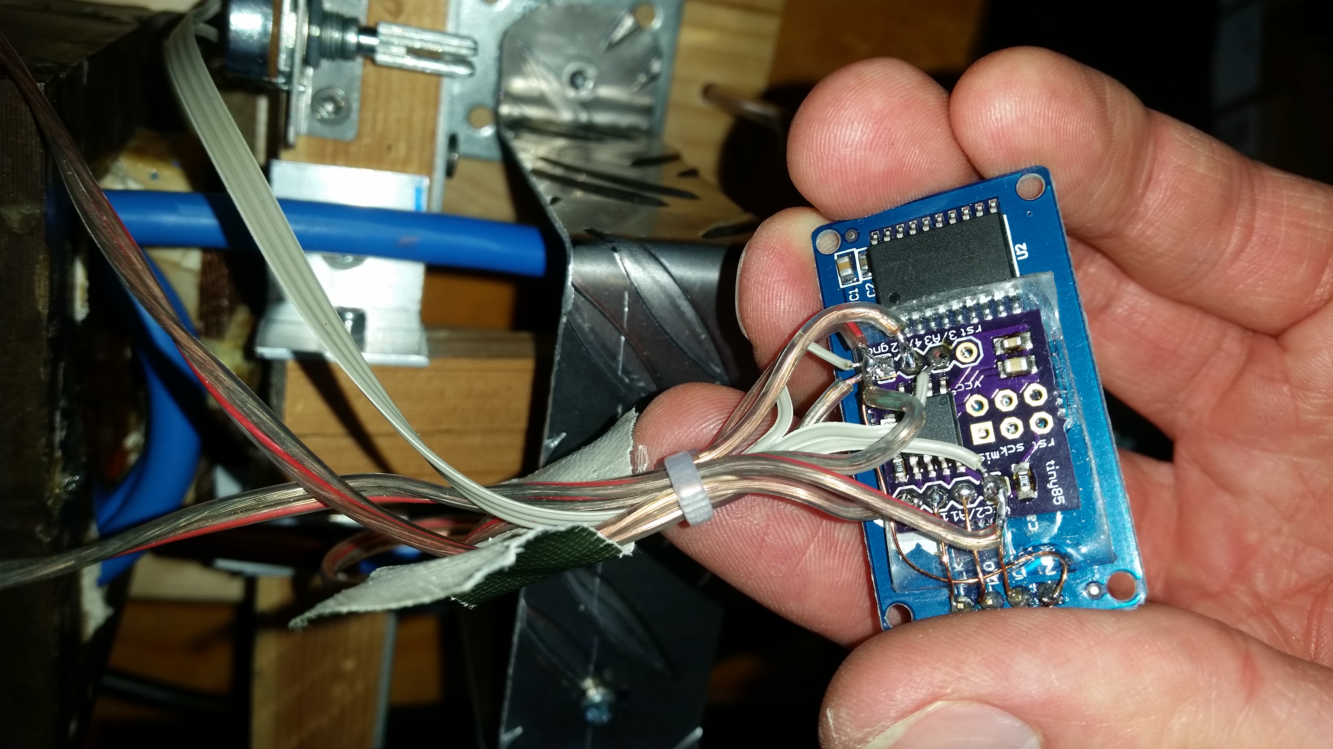
An Attiny85 breakout board takes care of pulse timing. The pulse duration can be adjusted with a 5k potentiometer. A TM1637-based 4 digit 7 segment display shows its duration in milliseconds. A solid state relay for AC voltage turns on the MOT for the set duration. The control circuit is powered by a small 5V 1A AC-DC converter of asian origin. All GPIO pins of the Tiny are finally occupied. The Attiny85 was programmed using the Arduino IDE and while the code is primitive, it does its job well:


//Spot welder controller, simple "blocking code using delays
//uses TM1637 4digit LED display board
//D2: data, D1: clock of TM1637
//D0: solid state relay to switch the MOT
//A3: potentiometer (5k to 50k)
//D4: trigger (2 microswitches in series for each welding electrode)


#include <Arduino.h>
#include <TM1637Display.h>

// Module connection pins (Digital Pins)
#define CLK 1
#define DIO 2
#define SSR 0
#define POT A3
#define TRIG 4

#define maxPulseLength 500

int weldingTimer = 400; //in ms
int pauseTimer = 4000;
int addr=0;
TM1637Display display(CLK, DIO);

void setup() {
  display.setBrightness(7);
  pinMode(TRIG, INPUT_PULLUP);
  pinMode(SSR, OUTPUT);
  digitalWrite(SSR,LOW);
  //value = EEPROM.read(addr);
}

void loop() {
  int anVal = analogRead(POT);
  weldingTimer=map(anVal,0,1024,0,maxPulseLength);
  display.showNumberDec(weldingTimer);

  if(digitalRead(TRIG)==LOW){
    digitalWrite(SSR,HIGH);
    delay(weldingTimer);
    digitalWrite(SSR,LOW);
    delay(pauseTimer);
  }
}

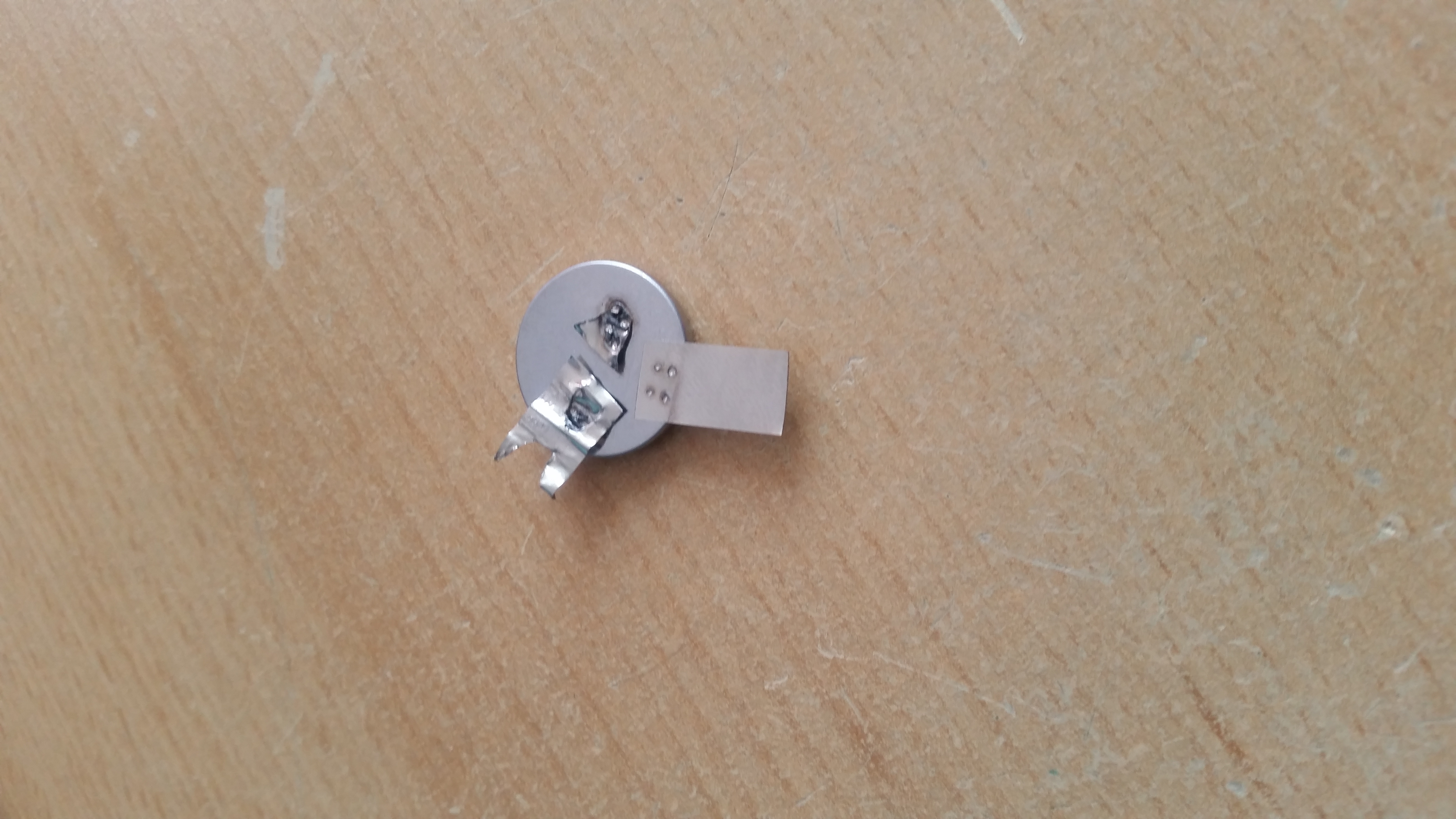
This system has plenty of power. It’s probably even over-powered for battery tab welding so make sure to start with small welding pulses of around 20ms and increase until the weld sticks well. With 70ms and an electrode distance of 3mm I managed to burn a hole through an empty coin cell in an attempt to weld a 0.1mm nickel strip to it. Experiment on scrap metal before you proceed to serious business such as 18650 cells.

Ebay 500W Wind Generator

Recently I’ve come across this high quality device while looking for a permanent magnet alternator to experiment with.
It’s supposed to be a generator designed particularly for wind turbines and able to deliver 500W. Not bad. Its weight is about 3.5kg. The shaft diameter is 20mm. That’s about all info I could get from the seller.


20161029_100500


The inner shaft diameter is 12mm, the 20mm slotted steel adapter can be taken off. It is sealed off with a plastic “bearing” with a steel spring around it (not visible in the picture). Could be polyethylene or similar to protect it from the elements. The chassis is supposedly cast aluminium at the front and a precision machined Al cover at the back with a chunky rubber ring between back cover and alternator. The alternator itself is a 90mm diameter high quality brushless outrunner motor/alternator by CPM with the entire stator potted in some kind of plastic. The rotor was made from machined steel. After visiting the webpage on the label you get forwarded to http://www.cpmotion.com/ A quick search for the part number was not successful.


20161029_095037


20161029_095149


The injection molded black plastic cover prevents the cables to touch the rotor of the alternator. Nice attention to detail. The black connector on the ribbon cable I have attached myself because I had a 20pin one lying around and 0.1 inch headers are much easier to work with.


20161029_095106


I got the thing from ebay (new and unused!) for less than 50€ and expected a 3phase device because of the three wires coming out of it. Instead it turned out to have a DC output (the yellow and green one is just tied to the chassis). After cranking it up by hand for testing I figured out that some charge was stored across the red and black wire which implied that there’s a capacitor hidden somewhere and that it had to be DC. The fact alone that the manufacturer had chosen red and black should actually be enough of a clue that it’s a DC device. Besides the power cables a 20pin connector with a ribbon cable is poking out of the enclosure as well. Asking the seller for datasheets was not successful. I was only told that it is worth much more than what I payed for it and that it’s from a company that went bankrupt. Visiting the website on the label did not give me a datasheet for this particular device either. The only thing I was able to find out is that the manufacturer (CPM) uses the CAN bus on their other products to control their devices (CAN 2.0A) besides some digital and analog pins on their control interfaces. At least something if we assume that not only the alternator but also the control electronics was designed by them.


So the only thing left is trying to reverse engineer it. After spinning the generator up with a drill you notice a very short pulse of mechanical resistance after a couple of turns. I thought maybe there is some kind of initialization routine happening after power-up. Attaching a 60W H4 automotive light bulb as a load showed that the device is definitely useful to generate DC electricity. The bulb could be brought to full brightness easily. A voltage measurement on different rpm without a load revealed that the voltage can easily go up to 48V.
After removing all screws I tried to open the front part but I couldn’t do it for some reason and therefore I decided to not do potentially irreversible stuff for now.


Instead the next reasonable step would be to crank the alternator up evenly with a drill and measure voltages on some pins. All we know to this point is that it’s likely to find a CAN interface on the header, which means that 2 pins should measure about 2.5V (depending on whether it’s 3.3V or 5V CAN) against some ground reference.
In the picture below you see the results of mapping out the interface.


20161029_094934


Indeed I was able to find -2.5V on the pins irrespective of RPM. Then I reversed polarity of my oscilloscope/multimeter and took the GND pin as a reference for further measurements. In total I was only able to find 2 pins with 2.5V which is another progress. 2 other pins had about 3.3V on them and 3 Pins had variable voltage (0-2V in my tests) depending on the RPM.


My ambition with this device is to try to communicate with it via CAN and try to repurpose its control electronics, as it seems to be well-engineered apparatus all in all. The fact that it has a pulse of resistance at startup makes it possible for this thing to have an internal, probably configurable load inside which might be used as a brake. Also I’m curious to know what kind of data it is capable to spit out. If I were the engineer, I’d probably have it measure power and RPM…let’s see. My approach will be to try to connect an Arduino via MCP2515 to the CAN pins and see whether I get any response.

DIY SMD Vacuum Tool

Especially when you are dealing with 0603 and smaller components and solder paste, even fine tweezers can become annoying because of their magnetic properties. I’ve looked at professional suction pick and place tools and noticed that the main parts they consist of can be found in my medical parts tray. A friend has kindly donated me a tiny “single-use” 3V vacuum pump which is used in wound treatment and I’ve decided to use this thing in this project. Fortunately you can buy them on ebay.


Other parts you’ll need is a drip infusion set, a pen or small 6mm pipe and syringe needles with a diameter of your choice. The green and yellow ones work fine for 0603 and smaller. Also you’ll need 2 AA batteries or one 18650 cell with the appropriate holder and a momentary switch to power the pump. The assembly is fairly easy.


smt suction pen

electric suction pen


The needles are shortened with a dremel, bent to shape and filed flat at the tip with a fine diamond file. You can easily change tips for different component sizes. The device is meant for double-handed operation, since you could be too inprecise on your pick and place hand if you had a switch directly on the pen. So you have the enclosure in the other hand and the pick and place madness can begin. Because the tip is far from air tight the part falls off immediately after you release the trigger. Oftentimes the adhesion to the solder paste on the PCB is even stronger than the suction.


smt components, vacuum pen and lead-free paste


I like attaching the component belts to the bill of materials that I’ve printed out so everything is in perfect order and every step of the process is clear and quick. Errors can be avoided that way.

LM3406 LED Driver Board

LM3406 LED driver


I was given a bunch of LM3406 1.5A switching buck converter led driver chips for evaluation purposes the other day. These chips make very powerful and efficient LED/laser diode drivers when used properly.
In order to make them useful a PCB had to be designed again, because the TSSOP14 package is too fine-pitched to prototype on a perfboard (as opposed to SOIC8). So I made an adjustable version with selectable output currents and had it manufactured by OSH Park.


LM3406 LED Driver Schematic


The trick behind the current adjustment is to have several sense resistors in parallel out of which certain ones can be added to or removed from the circuit via jumpers. The board is pretty versatile since you can add the appropriate resistors for currents you need and parallel them up if you are not able to find the right values. You don’t need to populate the entire row of resistors when a single fixed LED current is needed. Check out the data sheet for more information on sense resistor values.


In my current configuration you can select 300mA (no jumper), 700mA (only jumper in the middle populated) and 1000mA (all jumpers populated) and also some more exotic settings if you combine the jumpers differently.


Eagle board files:


LM3406 led driver

RF Detector 50MHz-3GHz

When working with RF modules that transmit/receive in the 2.4GHz or whatever range it’s sometimes useful to have some means to detect whether transmission really takes place. This wideband RF detector based on the LT5534 by Linear Technology is capable of doing so. Moreover it can tell, how strong the signal is, since its output ranges from 0V to VCC (5V in this case) and is proportional do the dBm of the received signal. The chip can be for free, which is what I did. The idea for this project as well as the first carrier board design was originally from Laboratory for Experimental Computer Science
at the Academy of Media Arts Cologne.


I improved the board a little and ordered some PCBs from OSH Park It takes about 2 weeks for them to arrive in Germany and costs almost nothing, since the boards, like the chip itself are tiny. Apart from the LT5534 itself the carrier board uses few standard components.


LT5534 rf detector carrier boards


To have an audiovisual output I decided to add a LM3914-based bar graph meter and a speaker with a TL072 opamp buffer, since I had both of them lying around luckily. I added the buffer because the LT5534’s output cannot deliver enough current to drive the speaker’s membrane adequately. What you hear is the raw modulation of the incoming RF signals. It’s like getting a 6th sense for the invisible RF pollution around you. For example if you hear periodic knocking sounds, it’s probably from a WiFi router.


RF RSSI 2


Here’s the preliminary breadboard version of the ciruit. The loop antenna was made for 2.4GHz but the device still receives signals over a pretty wide RF band. The PCB was designed specifically for the depicted enclosure. The carrier board will be connected to the bar graph board. The loop antenna will be replaced with a SMA jack with a coax cable pigtail to have the possibility to connect different antennas for different frequency ranges.


lt5534 rf detector on breadboard


DIY PCB ready to be built into the project box:


RF detector on DIY PCB


RF detector with DIY PCB


Now with loop antenna removed and SMA jack attached via coax pigtail.


RF detector on DIY PCB


Here are the modified schmatics and board files for the LT5534 carrier board:


LT5534 rf detector


Here is the board file and schematic for the bar graph and audio amplifier:


LM3914 rf signal strenth meter

Hydrostatic Pressure Sensor

I’ve recently found a single-use medical grade pressure sensor, as used in invasive catheter blood pressure measurements in critical care medicine.


It has got 4 output terminals as you can see in the picture below where one can simply insert small 1mm nails…


pressure sensor top


The internal configuration seems to be a Wheatstone Bridge and therefore it has to deliver an analog output. So some measurements of the resistances between the terminals were made which quickly led to the following test setup:


Pressure Sensor


pressure test setup


With 7.2V connected to the sensor the amplitude of the output voltage is at about 0.1V


A simple opamp-based differential amplifier was used to amplify the output.


20121022_234411