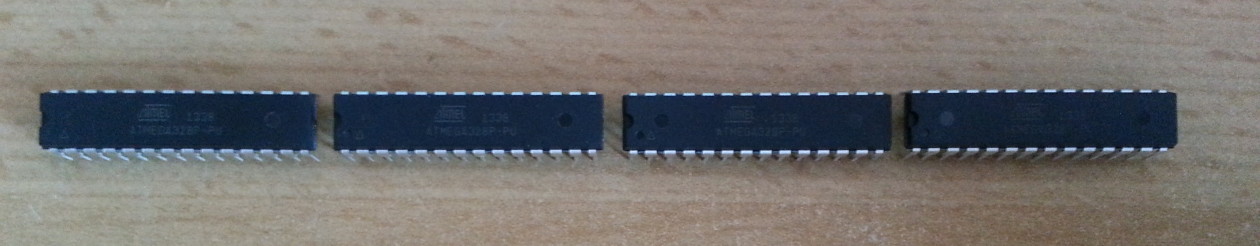
Having a reflow oven is a fantastic thing! Out of a sudden you can solder annoying IC packages with ease. I’ve been looking for a small and cheap ARM board with a 12bit ADC and low power options and came across the FRDM-KL05Z within the mbed envionment. This board only costs 11€ and besides the actual microcontroller (MKL05Z32VFM4) it has a MK20-based OpenSDA Interface which can do SWD and USB->UART on board which is a versatile tool for other microcontroller projects, in particular programming those cheap KL05Z chips. The mbed library has some example projects to demonstrate some things you can do with the chip, namely using different timers, the I2C accelerometer, PWM, interrupts and (very interesting) the built-in capacitive touch interface, which can also implement a slider. In conclusion, it’s a very interesting 32bit 48Mhz replacement for the Atmega328P which is used very often in small projects.
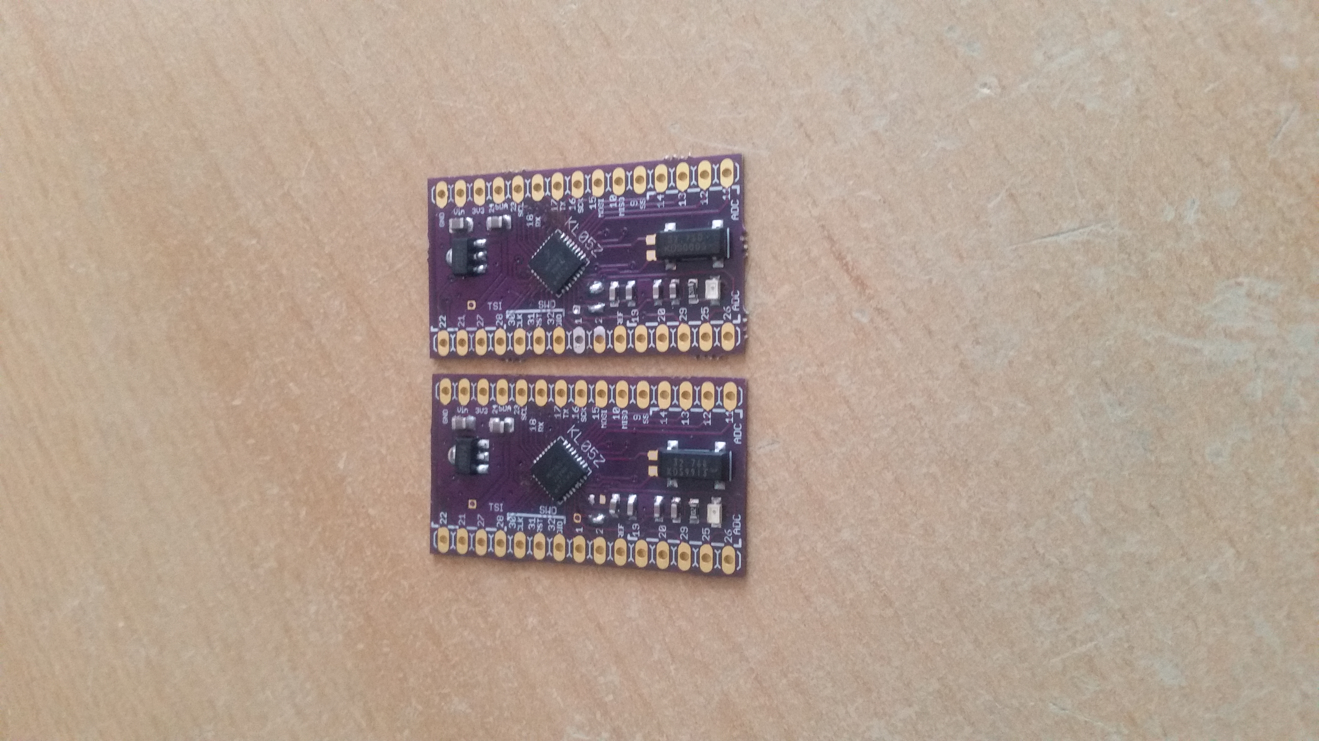
I’ve designed a board in eagle 7 (KL05Z design files) and ordered 3 samples from freescale. The board I had fabricated by OSH Park. The QFN32 (0.5mm pitch) reflowed really well with lead-free solder paste. Apply a thin string across each row of tiny pads, it doesn’t matter that the pads are “bridged”. The solder stop layer of the board and surface tension and flux of the paste resolve that for you. If you have bridges between the pads after reflowing, just apply a droplet of flux and touch them with the soldering iron tip. This corrects solder bridges easily without the use of solder wick! Yes, tiny pitch sizes have their advantages as well.
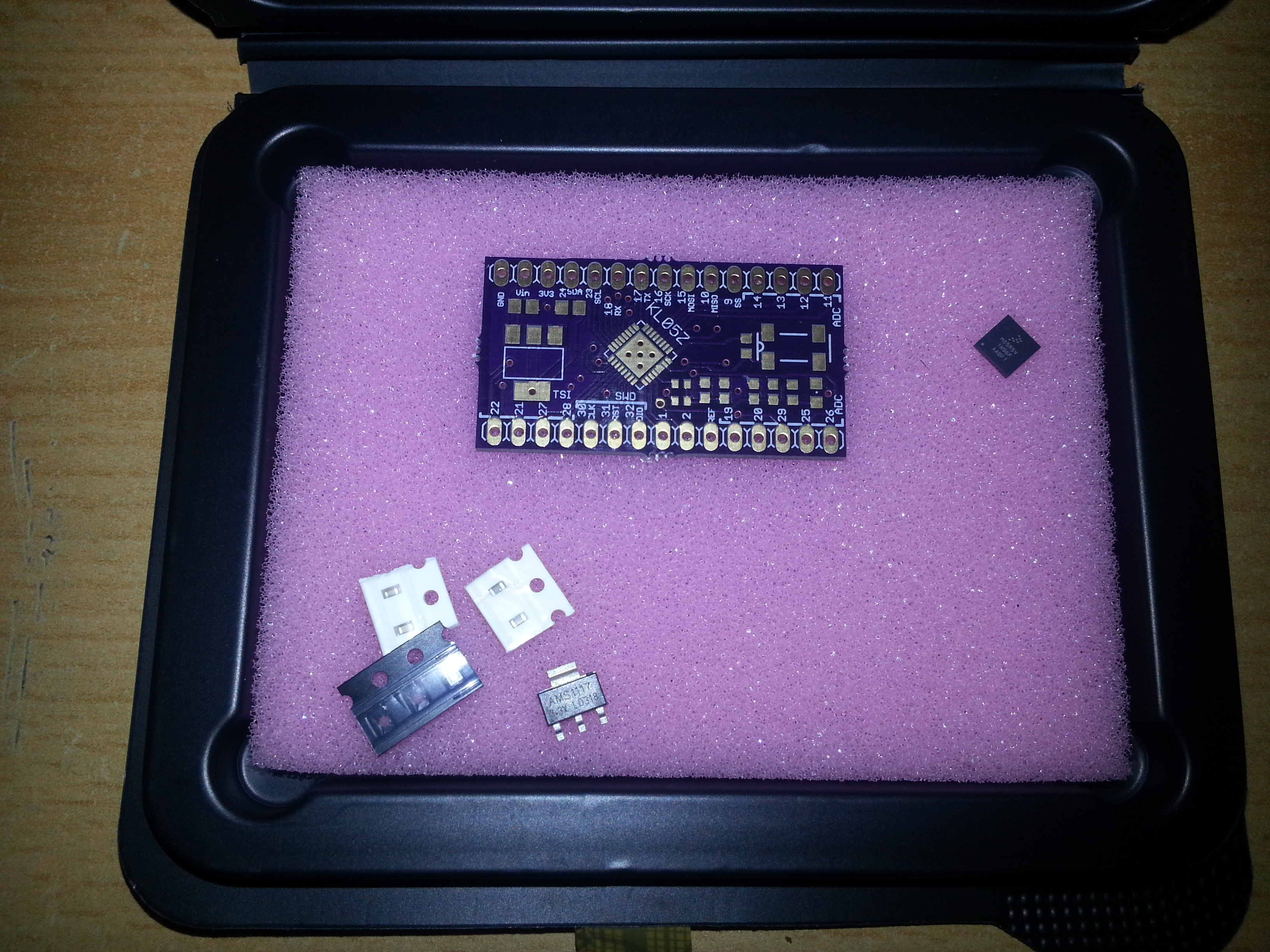
There are few other components on the board. 2 solder jumpers/0ohm resistors (the 0402 parts), 2x 1µF, 2x 100n (both 0603), 2x 10µF 0805, a 1k 0603 resistor, an 0603/0805 led at pin 11 (LED_RED in the mbed compiler), a voltage regulator and a watch crystal. Actually I didn’t quite feel the need of installing a reset button. You can hate me now for that………:-P But as there was plenty of room on the board, I built in a common AMS1117 3V3 regulator. Other voltages down to 1.8V can be dropped in as well. The footprint for the watch crystal allows a variety of different crystals to be intalled. No 22pf caps were installed in the FRDM board, so I left them out as well. The 10M resistor was included, but the circuit works fine without it. On the TOP side you have labels for pin numbers of the chips with their most common function within the mbed environment, while on the bottom side you find the port names of the pins. I haven’t included a 10-pin swd connector since the interface, besides power and ground, only consists of 3 pins (SWD_CLK, SWD_DIO and RST_TGTMCU) which you can connect with jumper wire just as easily. The wires for the three signals were soldered to J1 directly.

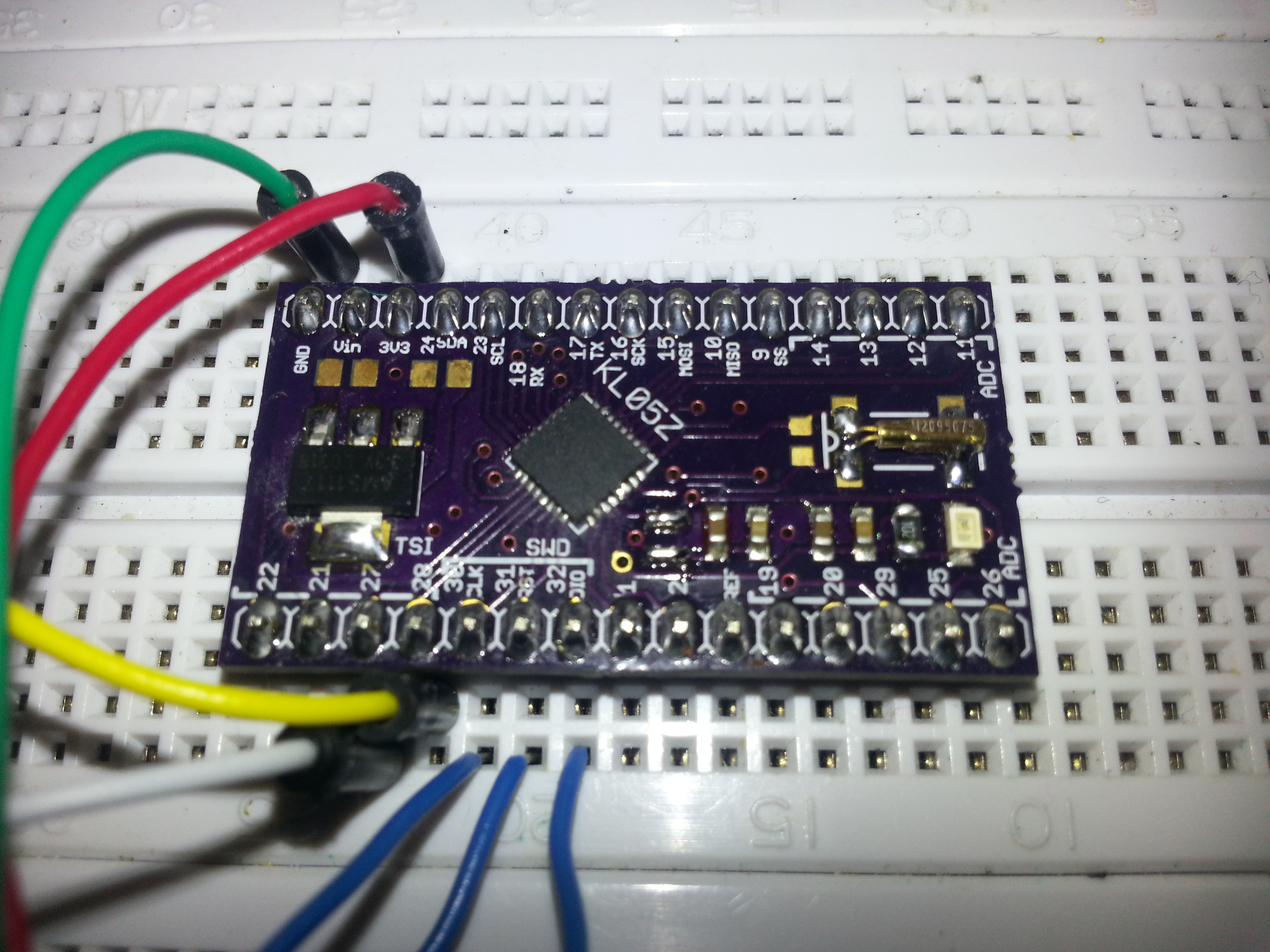
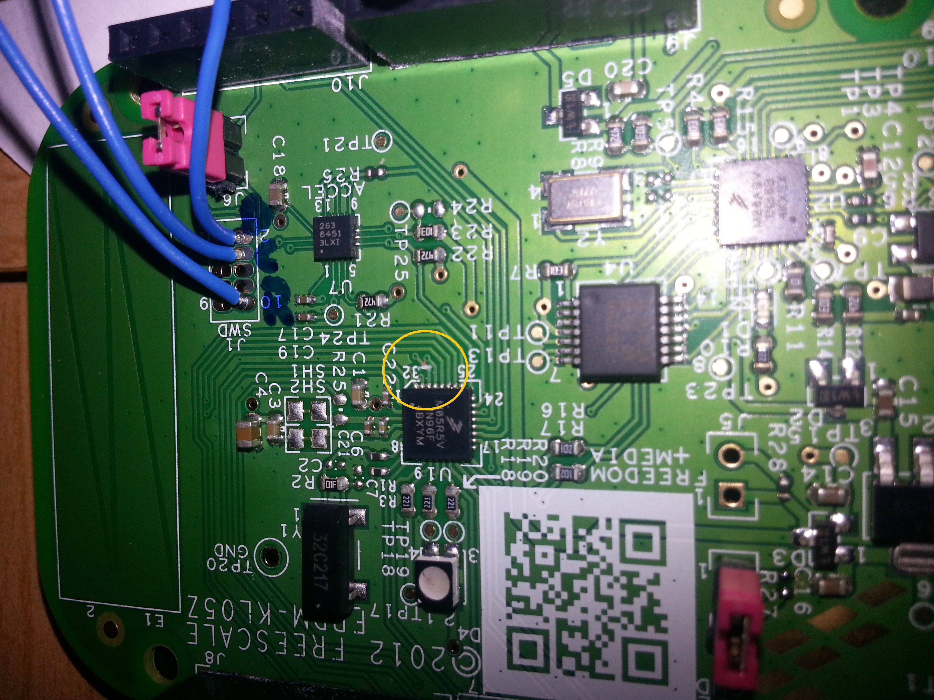
Programming can be done with a hacked FRDM board via mbed compiler. I’m saying hacked because there is a bug on the board that has to be fixed by cutting a trace in order to be able to program an off-board chip. By cutting a trace I don’t mean cutting the trace below the J6 jumper as the manual states. This jumper is completely useless! It’s supposed to disconnent the onboard target KL05Z from the SWD_CLK but it does not!! Just leave it in place and cut the trace right next to the MCU, running from pin 30 of the KL05Z to the next via (see the orange circle in the pic below):
Be very careful not to cut other traces. In case you’ll want to use the on board chip again, the solder mask on the trace will have to be exposed carefully an a tiny jumper will have to be inserted in some way. However at the moment I’m fine with my breakout boards.
Finally, a link to all relevant ducuments for the FRDM-KL05Z: FRDM-KL05Z freescale documentation page with schematics etc.
Update: improved and debugged version with a better voltage regulator:
KL05Z1.1