Category Archives: Arduino/Microcontrollers

builds and hacks including microcontrollers

Raspberry Pi Zero Lipo Fuel Gauge With Safe Shutdown

The Pi Zero (and Zero W) are quite tolerant in respect to their power requirements. They can even be run from a LiFePO4 battery that has a voltage range of 3.6 to 2.5V. LiPo batteries are better-suited as their voltage ranges from 4.2 down to about 3V. When running the boards from the blank cell (it should have protection circuitry!), they last even longer because fewer losses occur since there is no boost converter in the system. In fact, the 5V is only needed for the USB host, although many devices are supposed to work from voltages down to 3V.


Unfortunately, these single board computers lack power management and don’t have shutdown buttons and there are not that many simple and cost-effective solutions for these problems. https://www.tindie.com/products/xorbit/lifepo4weredpi/ is one nice example, but unfortunately not fully open source.
My idea was to combine a MAX17043 LiPo fuel gauge with a pushbutton and a LiPo charging circuit to create a battery and safe shutdown management add-on for the Pi Zero.


The little board occupies only the first 10 pins and uses only GPIO4 and SDA + SCL. Design files for the tiny custom TP4056 charger board can be downloaded as a .zip archive:


TP4056mCH

The Python script the make the thing work is attached below. Add it to rc.local to execute on startup.


#!/usr/bin/python

#Python Script for MAX17043 fuel gauge and safe shutdown button
#in order to execute on startup add the following line to /etc/rc.local
#(sleep 10;python /home/pi/fuelgauge.py) &
#assuming that fuelgauge.py is in /home/pi 
#sleep 10 is probably not necessary

import RPi.GPIO as GPIO
import smbus
import time
import os


#threshold in % below which the pi gets shut down
threshold=15.0
buttonPin=4
# I2C-Adddress of MAX17043
address = 0x36

#registers
VCELL_REGISTER=0x02
SOC_REGISTER=0x04
MODE_REGISTER=0x06
VERSION_REGISTER=0x08
CONFIG_REGISTER=0x0C
COMMAND_REGISTER=0xFE

#  open the bus by creating an instance
MAX17043 = smbus.SMBus(1)

#set up GPIO for shutdown button
GPIO.setmode(GPIO.BCM)
#Using GPIO nr 4
GPIO.setup(buttonPin,GPIO.IN,pull_up_down=GPIO.PUD_UP)

def reset():
    MAX17043.write_byte_data(address, COMMAND_REGISTER, 0x00)
    MAX17043.write_byte_data(address, COMMAND_REGISTER, 0x04)

def quickStart():
    MAX17043.write_byte_data(address, MODE_REGISTER, 0x40)
    MAX17043.write_byte_data(address, MODE_REGISTER, 0x00)

#get state of charge
def getSOC():
    # Konfiguration des MAX17043
    MSB= MAX17043.read_byte_data(address, SOC_REGISTER)
    LSB = MAX17043.read_byte_data(address, SOC_REGISTER)
    percentage= MSB+ LSB/256.0
    #print percentage
    if percentage < threshold:
        os.system("sudo shutdown -h now")


#Arduino map function for convenience
def arduino_map(x, in_min, in_max, out_min, out_max):
    return (x - in_min) * (out_max - out_min) // (in_max - in_min) + out_min

#setup
reset()
quickStart()

# Loop
while True:
    getSOC()
    time.sleep(1.5)
    #shutdown if button is pressed and held
    if (GPIO.input(buttonPin)==0):
        os.system("sudo shutdown -h now")


if __name__ == "__main__":
   main()


Pulse Oximeter Hack

The pulse oximeter is a very useful and affordable medical gadget. It incorporates a quick and easy way of measuring your heart rate as well as calculating the blood oxygen saturation in one go! After having a look inside the Contec CMS50C and CMS50D which are both MSP430-based devices with OLED displays, it quickly became apparent, which one is easier to hack to extract the data.


The CMS50C (the one with the color OLED, available for <15$ on the usual platforms) has a nice line of well accessible and labeled pads, among which is also a UART interface that is streaming all of the useful values such as 7bit photoplethismographic curve data, the "bar graph", the SPO2 and heart rate value, a "beat detection bit" and various diagnostic bits at a sampling rate of 60Hz. An overview over the entire communication protocol can be found here. The serial port settings are a bit unusual: 4800 baud, and EVEN parity, so watch out for that, but other than that it’s a quite clever protocol that is storing all this information in only 5 bytes.


The most essential connections are GND, TX, RST, the right pin of the trigger pushbutton and Batt. After that you should be able to completely control the thing from a microcontroller and harvest the data.
A code sample for Teensy 3.x is found below:


//sketch for reading the CMS50C pulse oximeter data using a Teensy 3.x

#define TRIG_PULSEOX 3 // has to be pulled to 3.3V to start the CMS50C
#define RST_PULSEOX 15
//vars for pulseOx
char incomingPulseOxbyte;
unsigned int byteCntPulse = 0;
char pulseCurve_PulseOx = 0;
char SPO2;
char HR_PulseOx;
boolean lastBitPulseOx = 0; //the MSB of the heart rate byte is hidden in a different byte - the one that holds the bar graph data
unsigned long pulseOxTrigTmr=0;
unsigned long pulseOxTrigInt=600000; // length of the pulse that triggers the CMS50C
unsigned long pulseOxRstTmr=0;
unsigned long pulseOxRstInt=800000;

boolean triggeredOx = false;
boolean resettedOx = false;

//packet management bytes for the Amarino Android app
char startFlag = 18;
char ack = 19;
char delimiter = 59; //';' in case we use more than 1 channel


void setup() {
  // put your setup code here, to run once:
  Serial1.begin(115200); // Bluetooth port
  Serial3.begin(4800, SERIAL_8E1); // Pulse oximeter CONTEC CMS 50C, annoying fact: it has EVEN PARITY!

   // make the pins outputs:
  pinMode(RST_PULSEOX, OUTPUT);
  pinMode(TRIG_PULSEOX, OUTPUT);
  
  digitalWrite(RST_PULSEOX, HIGH);
  
  
  triggerOx(); //turn on the PulseOx

}

void loop() {

  
  // put your main code here, to run repeatedly:
   //waiting to pull TRIG_PULSEOX LOW again 
  if((micros()-pulseOxTrigTmr)>pulseOxTrigInt && triggeredOx == true){
    digitalWrite(TRIG_PULSEOX, LOW);
    triggeredOx=false;
  }
  

   readPulseOx();

}

void readPulseOx() {
 
  //--------------------Pulse Oximeter data analysis----------------
  if (Serial3.available() > 0) {
    //pulseox data
    incomingPulseOxbyte = Serial3.read();
    if (byteCntPulse == 1) {
      //the second byte contains a 7 bit pulse wave value, Fs=60Hz
      pulseCurve_PulseOx = incomingPulseOxbyte;
      byteCntPulse++;
    } else if (byteCntPulse == 2) {
      //the 0-3rd bits of the third byte is the bar graph value .
      //the 6th bit is bit 7 of the heart rate value!
      if ( bitRead(incomingPulseOxbyte, 6)) {
        //if the heart rate is >= 128, this happens
        lastBitPulseOx = 1;
      } else
        lastBitPulseOx = 0;

      byteCntPulse++; //move on
    } else if (byteCntPulse == 3) {
      //
      if (lastBitPulseOx)
        //if the heart rate is >= 128, this happens
        HR_PulseOx = 128 + incomingPulseOxbyte;
      else
        HR_PulseOx = incomingPulseOxbyte;

      byteCntPulse++;
    } else if (byteCntPulse == 4) {
      //the last byte contains the most important SPO2 value
      SPO2 = incomingPulseOxbyte;
      byteCntPulse = 0; //we're done the data packet has 5 bytes in total
    } else {


      Serial1.print(startFlag);
      Serial1.print("P");
      Serial1.print(delimiter);
      Serial1.print(pulseCurve_PulseOx, DEC); //send the pulse curve value
      Serial1.print(delimiter);
      Serial1.print(HR_PulseOx, DEC); //send the heart rate
      Serial1.print(delimiter);
      Serial1.print(SPO2, DEC); //send SPO2 value!
      Serial1.print(ack);

    }

    //analyze the first byte. it has plenty of information about the data
    //the fourth bit of the first packet byte means "OK signal" if zero, otherwise it stands for "searching too long"
    //the seventh bit of the first byte has to be always set!!!!! (the only byte where this is the case) all other bytes have a bit 7 == 0
    if ( bitRead(incomingPulseOxbyte, 7)) {
      byteCntPulse++;
    }
  }

}

void triggerOx(){
//function to trigger the pulse oximeter button
   digitalWrite(TRIG_PULSEOX,HIGH);
   pulseOxTrigTmr=micros();
   triggeredOx=true;
 }


Better Blood Pressure Monitor Hack

After ordering the cheapest (wrist-type) blood pressure monitor I could find online (around 10$) to see how it performs in comparison to a “regular one”, I got a nice surprise.


I’ve hooked up a logic analyzer to as many testpoints on its PCB as possible and found out that it has a UART interface on board!! How convenient is that?
This ABP hack has proven to be quite impractical after all, although many people have shown interest in this this project and contacted me as it’s quite useful to have access to your blood pressure data and almost no open source blood pressure monitor projects exist.


A sequence of bytes is sent from testpoint “P6” which turns out to be UART TXD @9600 baud 8N1. You can hook up ANY microcontroller to that and harvest the data easily. After a measurement is complete and successful, the device keeps sending the same byte sequence over and over again until powerdown.


This sequence is the one you see on the pictures: 255 – 254 – 008 – x – x – 0 – Syst. RR low byte – Syst. RR high byte – Diast. RR – heart rate.  As you can see the last 4 bytes of the frame is our desired data. For the systolic pressure we seem to require 2 bytes because 255 is apparently not enough. Sad but true 🙂 , then comes the diastolic pressure and finally the heart rate. The frame starts with 3 fixed bytes (255, 254 and 008 in decimal), followed by 2 variable bytes (haven’t figured out what those are for yet) and a zero byte followed by the data.


Throughout the measurement process itself constantly pressure data is streamed via UART. Each data packet begins with a ‘254’ (DEC) byte followed by one “cuff pressure” byte and one byte that represents the pulse oscillation.  Here’s what the data of one measuring cycle looks like if plotted over time:


2 JST connectors were inserted into the enclosure. The 3 pin one gives you access to GND, the ON/OFF/START button to remotely trigger the device (just has to be pulled to GND) and finally to the TXD pin of the device. The 2 pin one is simply connected to the battery terminals to eliminate the need for batteries and power the thing from an external source.


Just look online for sphyngomanometers of similar appearance if you want to hack one too. This one has “CK” as a logo, but there are models around from different brands that look the same enclosure-wise. The exact model name of this device is “CK-101”


These devices perform reproducible values but you have to make sure to keep your wrist at heart level, as otherwise the values vary extremely. There is also literature that suggests that the wrist-type sphyngomanometers overestimate blood pressure because of distinct anatomical properties of the wrist arteries (https://www.ncbi.nlm.nih.gov/pubmed/15096904).


One application for an automatically triggered wrist sphyngomanometer I can think of is automated sleep measurement because during sleep your wrist is roughly at heart level anyway.

Ebay 500W Wind Generator

Recently I’ve come across this high quality device while looking for a permanent magnet alternator to experiment with.
It’s supposed to be a generator designed particularly for wind turbines and able to deliver 500W. Not bad. Its weight is about 3.5kg. The shaft diameter is 20mm. That’s about all info I could get from the seller.


20161029_100500


The inner shaft diameter is 12mm, the 20mm slotted steel adapter can be taken off. It is sealed off with a plastic “bearing” with a steel spring around it (not visible in the picture). Could be polyethylene or similar to protect it from the elements. The chassis is supposedly cast aluminium at the front and a precision machined Al cover at the back with a chunky rubber ring between back cover and alternator. The alternator itself is a 90mm diameter high quality brushless outrunner motor/alternator by CPM with the entire stator potted in some kind of plastic. The rotor was made from machined steel. After visiting the webpage on the label you get forwarded to http://www.cpmotion.com/ A quick search for the part number was not successful.


20161029_095037


20161029_095149


The injection molded black plastic cover prevents the cables to touch the rotor of the alternator. Nice attention to detail. The black connector on the ribbon cable I have attached myself because I had a 20pin one lying around and 0.1 inch headers are much easier to work with.


20161029_095106


I got the thing from ebay (new and unused!) for less than 50€ and expected a 3phase device because of the three wires coming out of it. Instead it turned out to have a DC output (the yellow and green one is just tied to the chassis). After cranking it up by hand for testing I figured out that some charge was stored across the red and black wire which implied that there’s a capacitor hidden somewhere and that it had to be DC. The fact alone that the manufacturer had chosen red and black should actually be enough of a clue that it’s a DC device. Besides the power cables a 20pin connector with a ribbon cable is poking out of the enclosure as well. Asking the seller for datasheets was not successful. I was only told that it is worth much more than what I payed for it and that it’s from a company that went bankrupt. Visiting the website on the label did not give me a datasheet for this particular device either. The only thing I was able to find out is that the manufacturer (CPM) uses the CAN bus on their other products to control their devices (CAN 2.0A) besides some digital and analog pins on their control interfaces. At least something if we assume that not only the alternator but also the control electronics was designed by them.


So the only thing left is trying to reverse engineer it. After spinning the generator up with a drill you notice a very short pulse of mechanical resistance after a couple of turns. I thought maybe there is some kind of initialization routine happening after power-up. Attaching a 60W H4 automotive light bulb as a load showed that the device is definitely useful to generate DC electricity. The bulb could be brought to full brightness easily. A voltage measurement on different rpm without a load revealed that the voltage can easily go up to 48V.
After removing all screws I tried to open the front part but I couldn’t do it for some reason and therefore I decided to not do potentially irreversible stuff for now.


Instead the next reasonable step would be to crank the alternator up evenly with a drill and measure voltages on some pins. All we know to this point is that it’s likely to find a CAN interface on the header, which means that 2 pins should measure about 2.5V (depending on whether it’s 3.3V or 5V CAN) against some ground reference.
In the picture below you see the results of mapping out the interface.


20161029_094934


Indeed I was able to find -2.5V on the pins irrespective of RPM. Then I reversed polarity of my oscilloscope/multimeter and took the GND pin as a reference for further measurements. In total I was only able to find 2 pins with 2.5V which is another progress. 2 other pins had about 3.3V on them and 3 Pins had variable voltage (0-2V in my tests) depending on the RPM.


My ambition with this device is to try to communicate with it via CAN and try to repurpose its control electronics, as it seems to be well-engineered apparatus all in all. The fact that it has a pulse of resistance at startup makes it possible for this thing to have an internal, probably configurable load inside which might be used as a brake. Also I’m curious to know what kind of data it is capable to spit out. If I were the engineer, I’d probably have it measure power and RPM…let’s see. My approach will be to try to connect an Arduino via MCP2515 to the CAN pins and see whether I get any response.

Homebrew OpenBCI V3 and Ultracortex

I’ve been intrigued by the ADS1299 chip by TI for a long time and after I came across the OpenBCI project and felt that my SMT skills were good enough, I finally decided to give the DIY approach a trial. The documentation is very good and almost complete and everything is open source, so get ready for an exciting blog post.
First off I downloaded Design Spark, which is the PCB editor the OpenBCI designs were made with. I used it to generate gerber files for getting the boards and solder paste stencils manufactured by OSH Park. By now they even have a function for importing Design Spark files.
Anyway, here are the Gerber files for the OpenBCI V3 8bit board. You should be able to place OSH orders using these:
OpenBCI 8bit OSH Park
For OSH Stencils:
OpenBCI 8bit OSH Stencils working
32bit Gerbers:
OpenBCI 32bit
32bit board stencil Gerbers:
OpenBCI 32bit Stencil
Daisy Board Gerbers (the 8bit board stencil partially fits the Daisy board, therefore I didn’t generate stencil Gerbers for that):
OpenBCI_Daisy

Note that there’s a bug on the Daisy PCB, which is described here.
luckily I knew about that issue and fixed it during the “pick and place” process prior to soldering.

I would recommend building the 32bit version right away since it is more capable (writes to SD, can be upgraded to 16 channels, fewer power rails, runs from one lithium cell, no need for 5V+, better microcontroller and last but not least: easier to build since it has fewer parts!).

Most parts were sourced from Digikey and Mouser. The SD card holder I found somewhere on ebay.
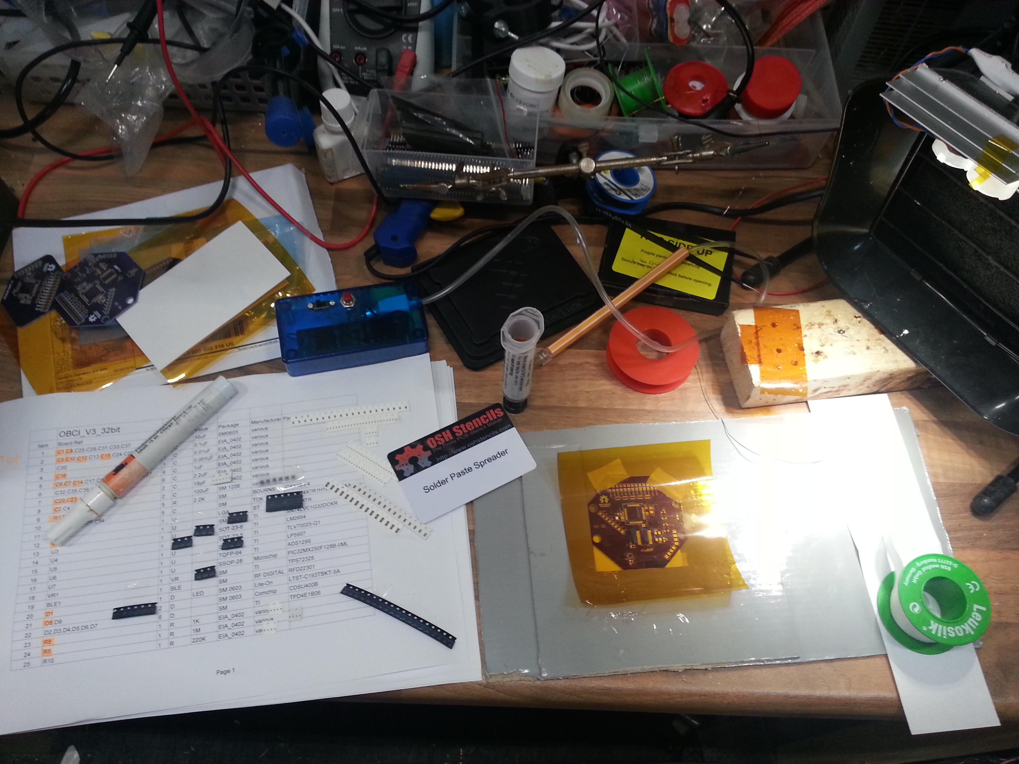
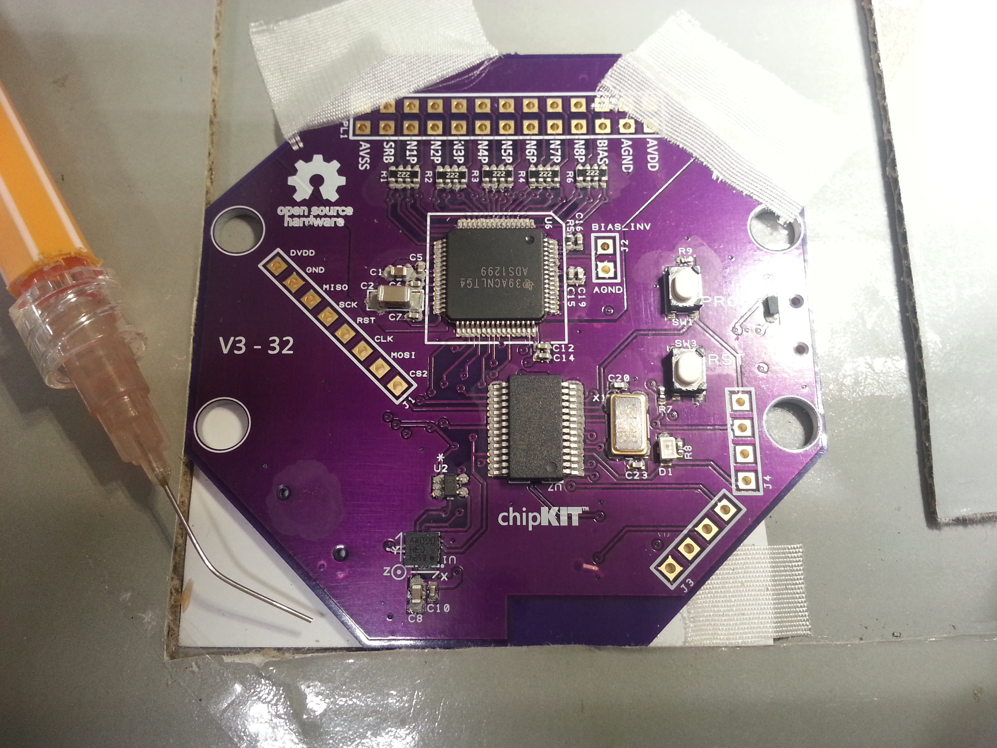
Also, I found picking and placing of tiny 0402 parts worked best with my DIY SMD vacuum tool and a thin needle. Especially where the components are densely packed (below the ADS1299) this method was very helpful. Before you begin, make sure to print out the OpenBCI_32bit_BOM and stick the component tapes with gluestick or sticky tape right next to the part indices. That way no parts get lost and you know exactly where each one belongs.

20160613_163743

20160613_164020

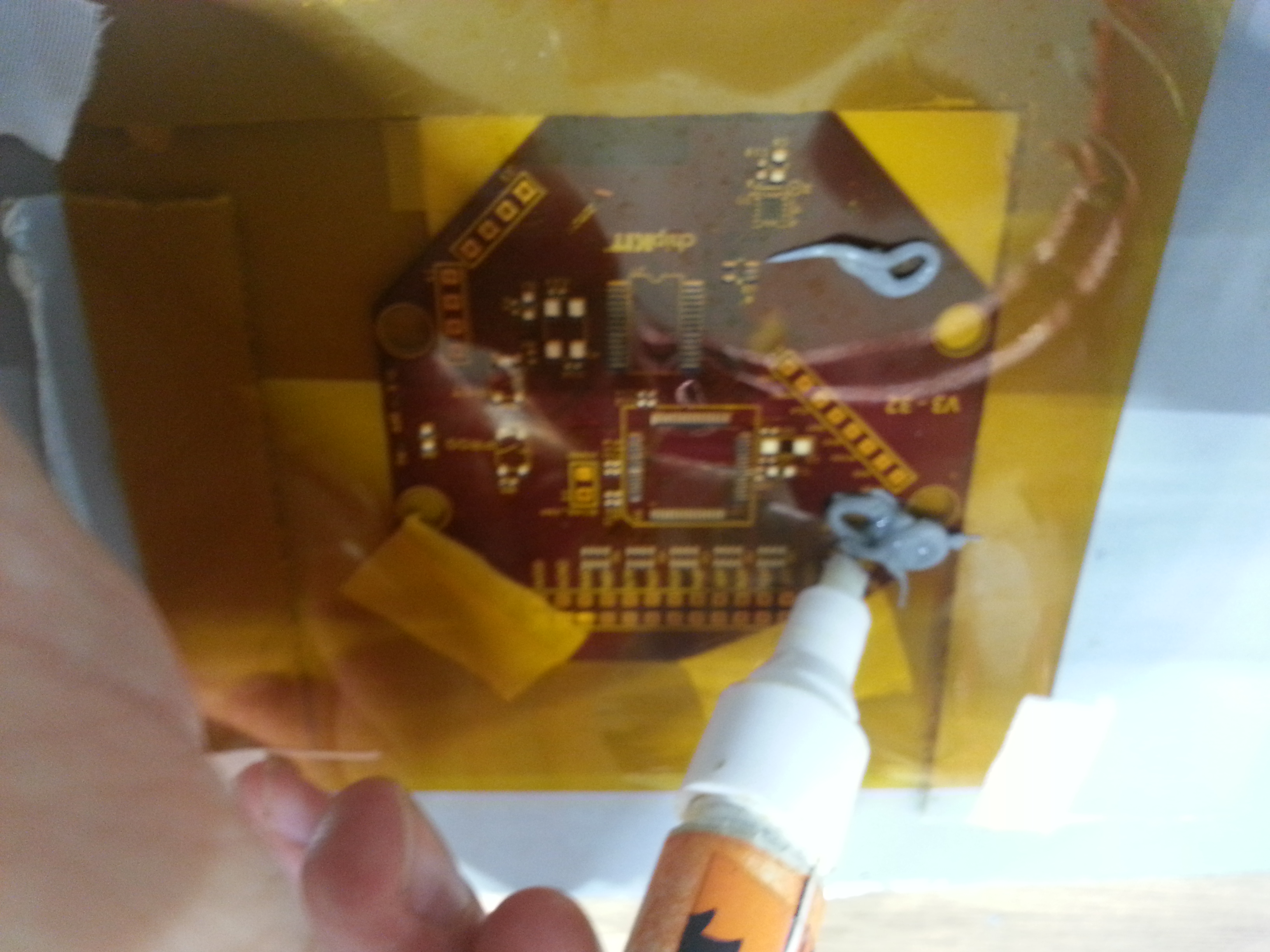
I had better results adding a drop a thin flux from a flux pen into the solder paste and mixing it. That way the solder paste is a bit smoother and reflows better. Remember: you can never use too much flux!

20160613_164152

20160613_164534

20160613_170951

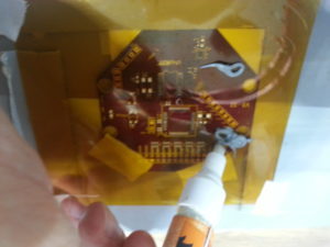
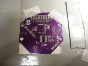
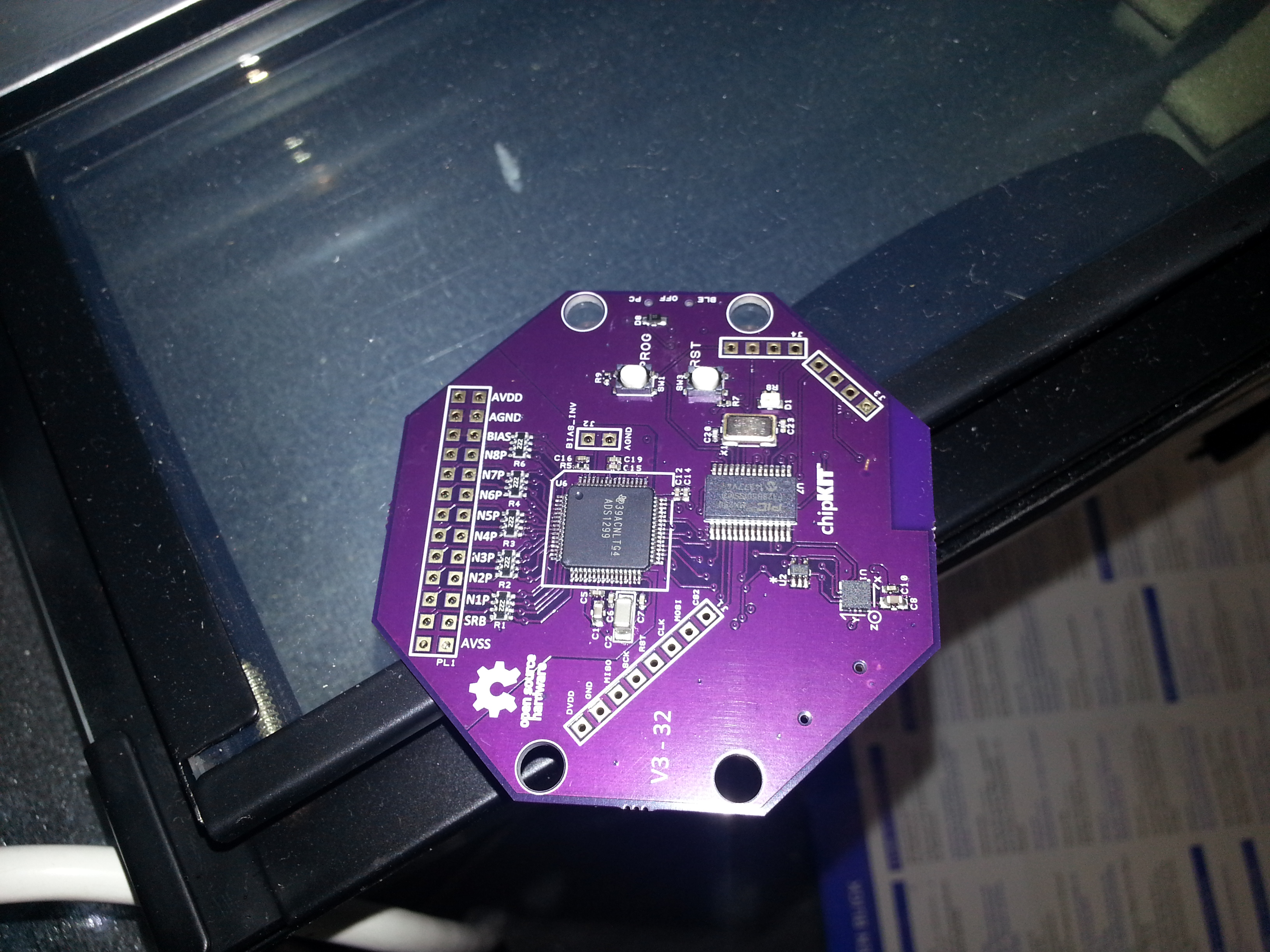
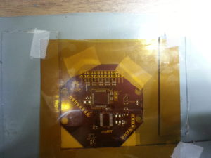
The top side goes into the DIY reflow oven

20160613_171929

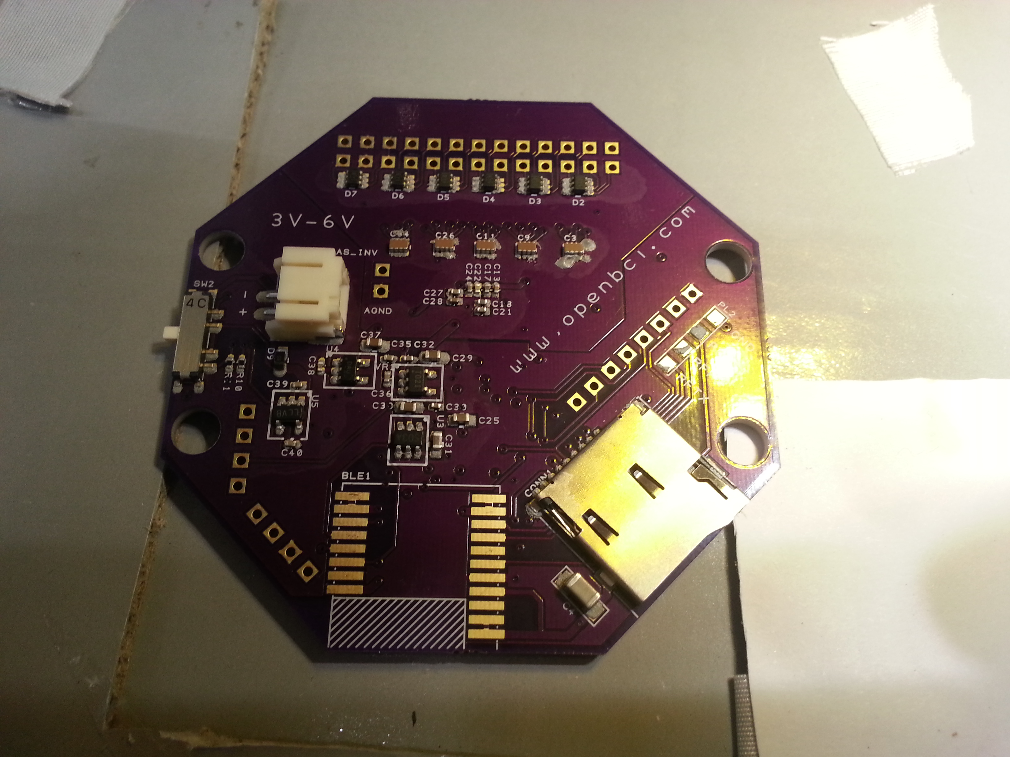
The bottom side is soldered with a hot air tool, being careful not to overheat the PCB.

20160613_175840

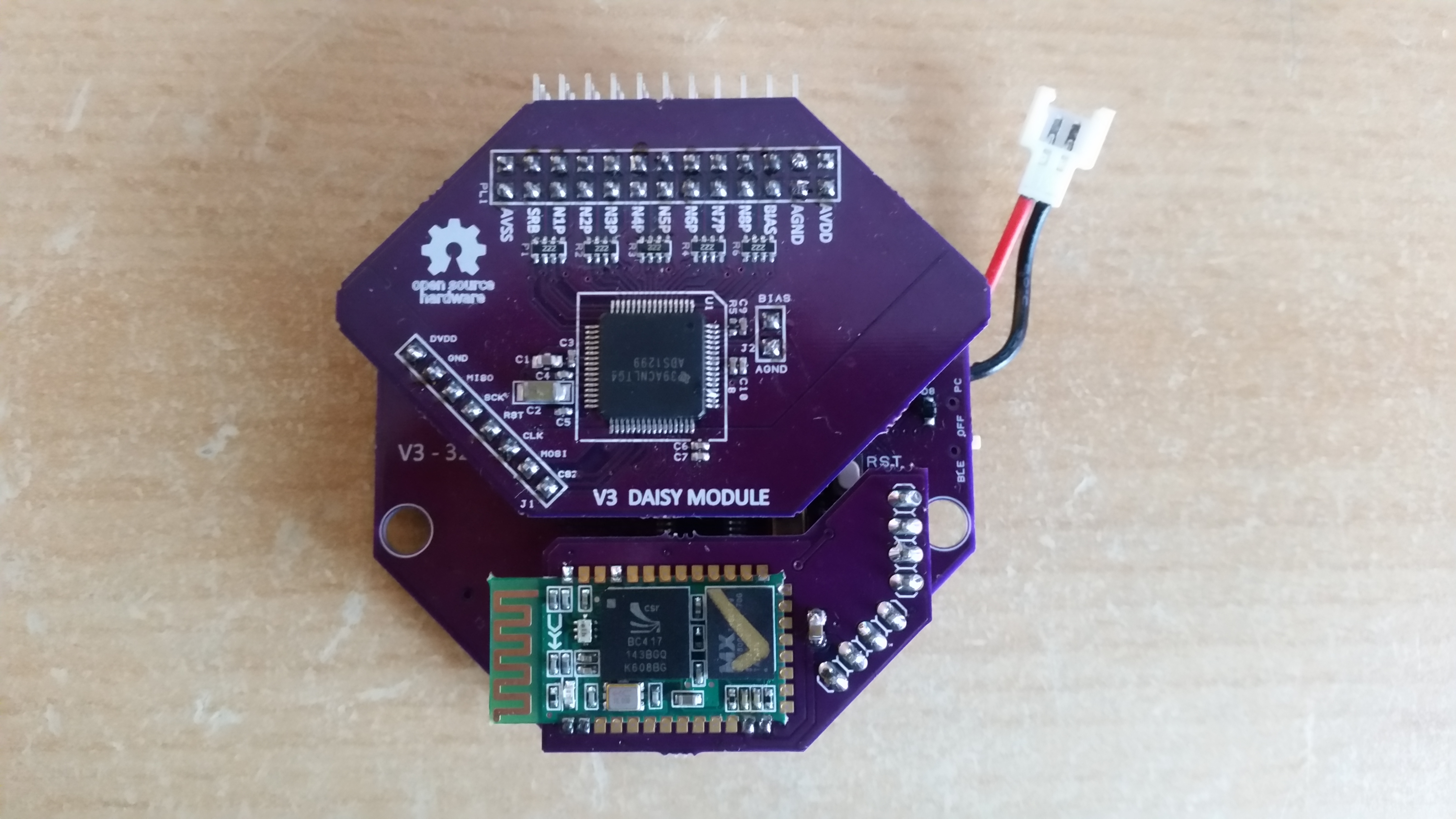
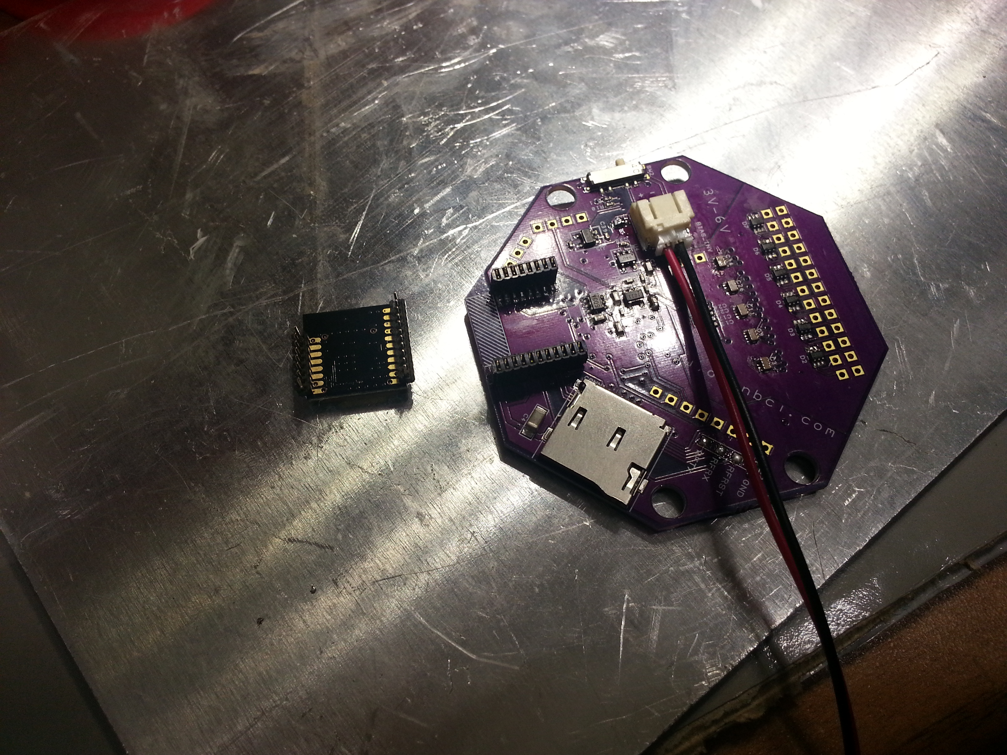
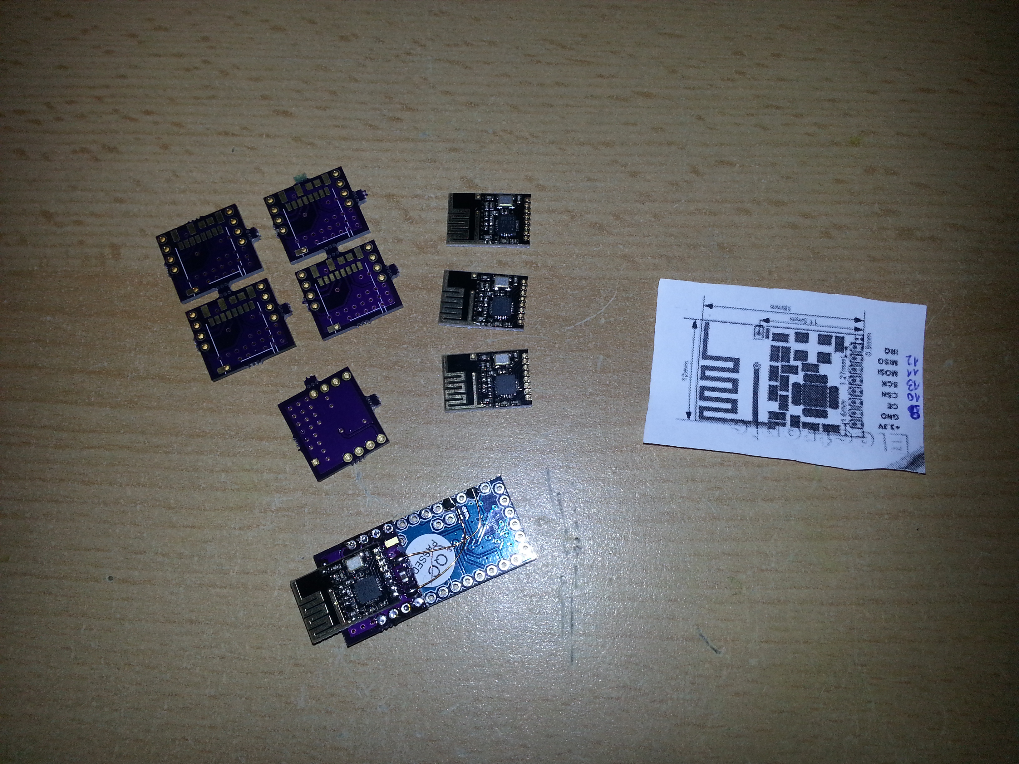
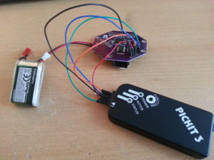
I’ve soldered 1.27mm header pins to the RFduino and female headers to the PCB because the wireless link is the bottleneck of the system. The headers allow to connect a different wireless module such as BT 2.1 or a USB-serial converter, which could be useful when planning to increase the sampling rate or using the system with Android devices.

20160613_185014

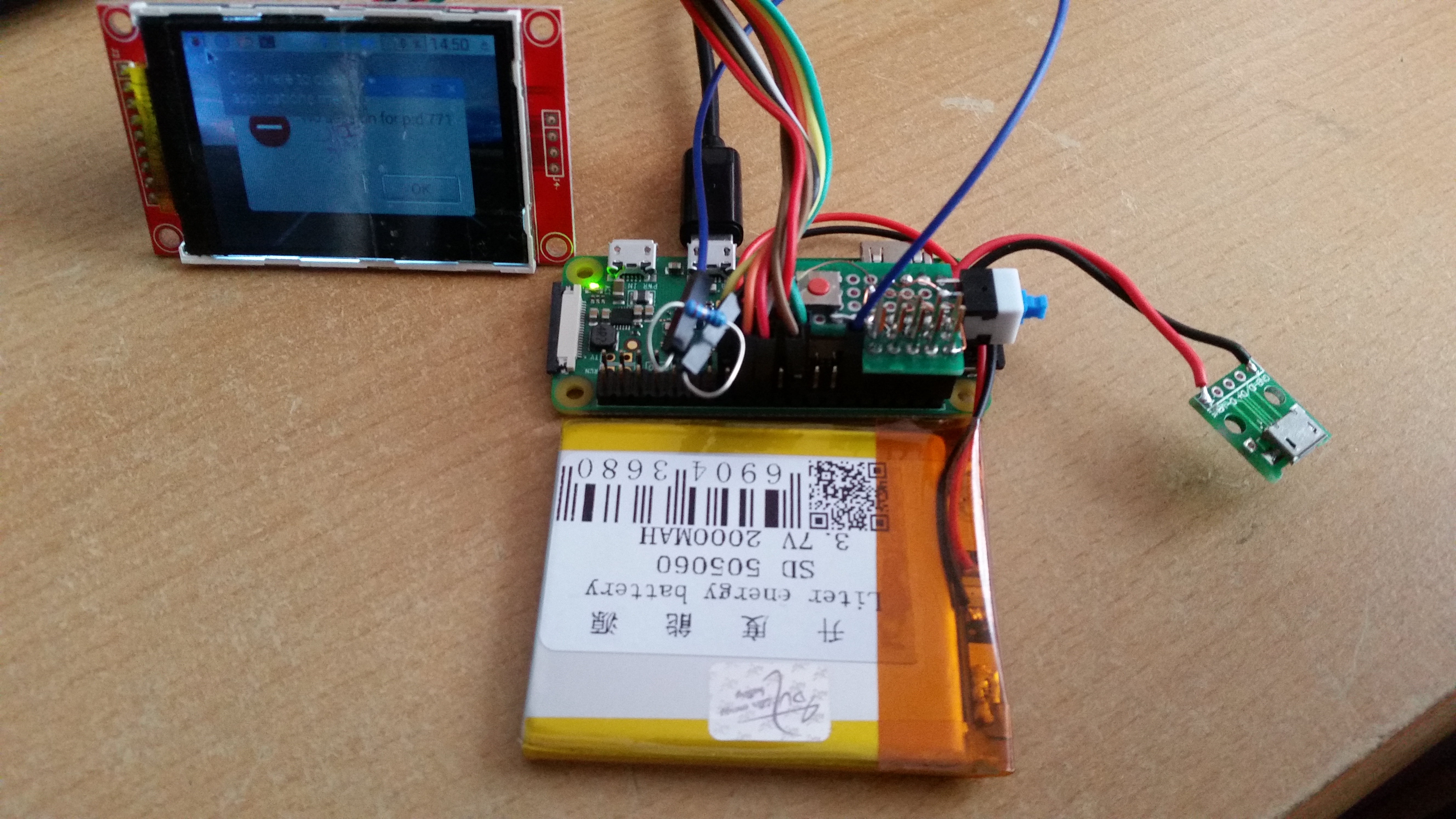
Using the PICKIT 3 programmer and MPLAB IPE (you can install ithe IPE without installing the IDE) to flash the Chipkit bootloader (can be found in the OpenBCI Github repository).

20160613_191010

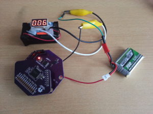
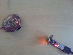
The current draw of the 32bit board is about 60 mA

20160614_105347

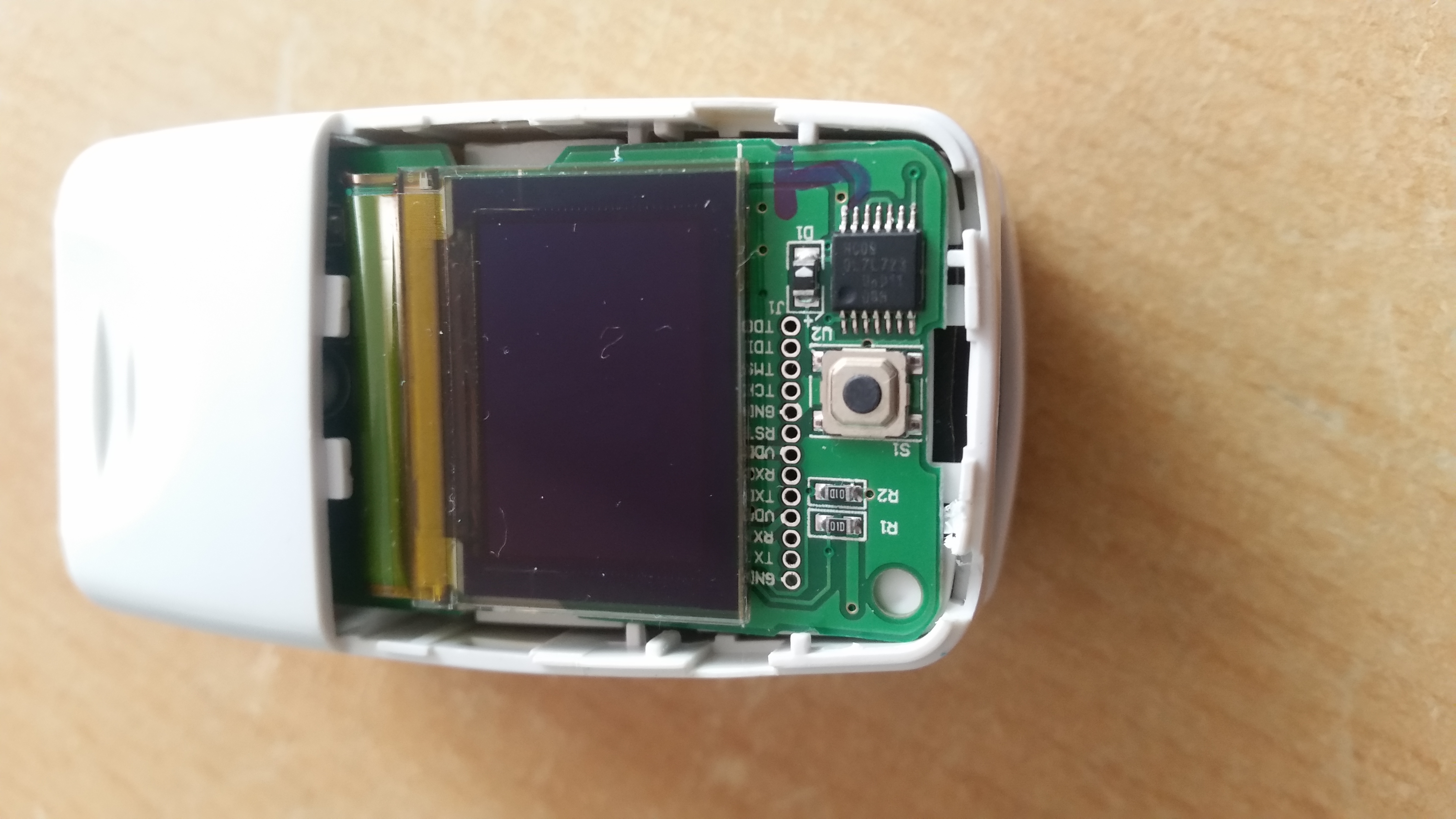
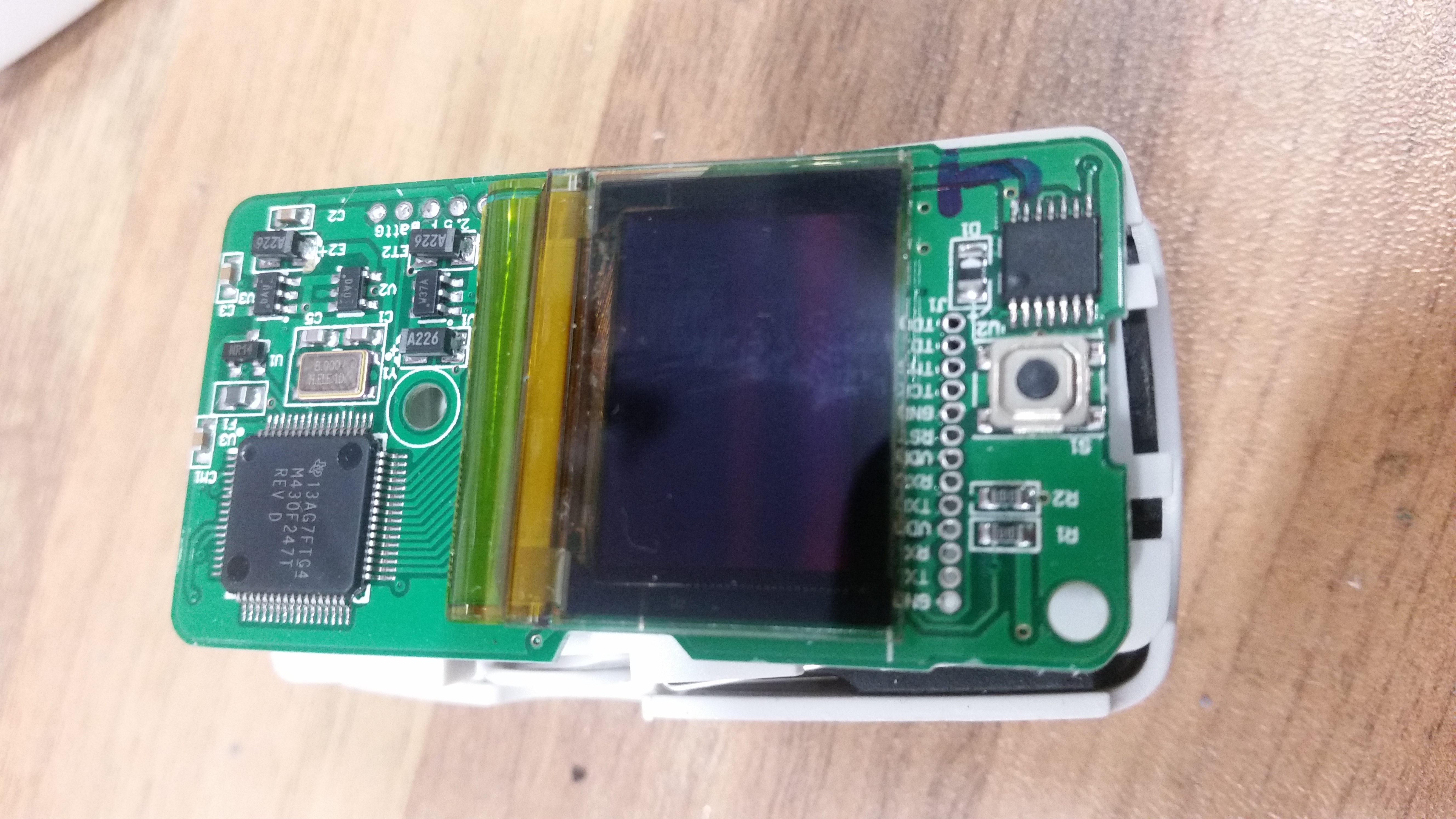
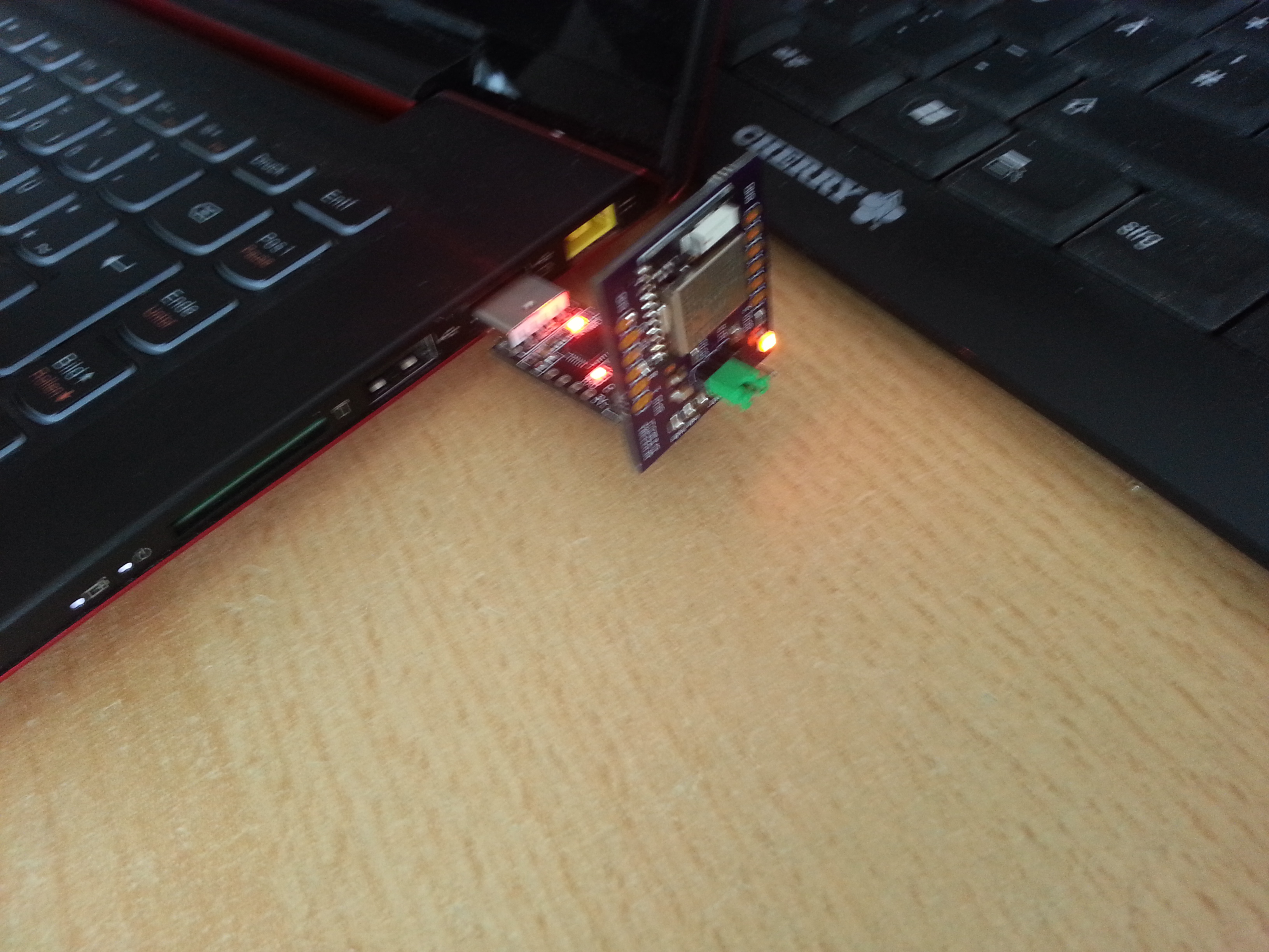
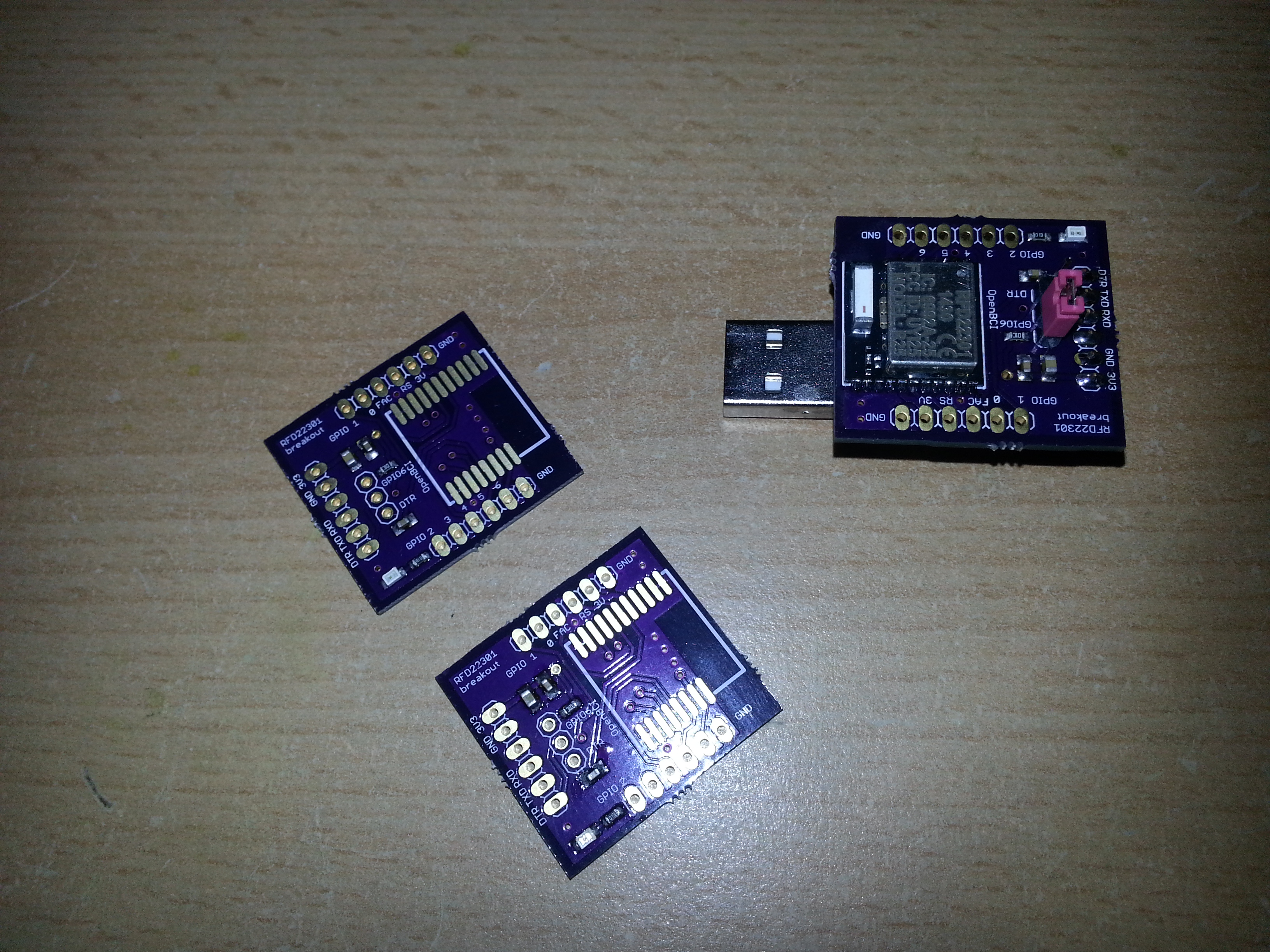
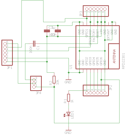
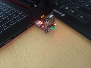
My own dongle design:

20160614_105403

20160613_193246

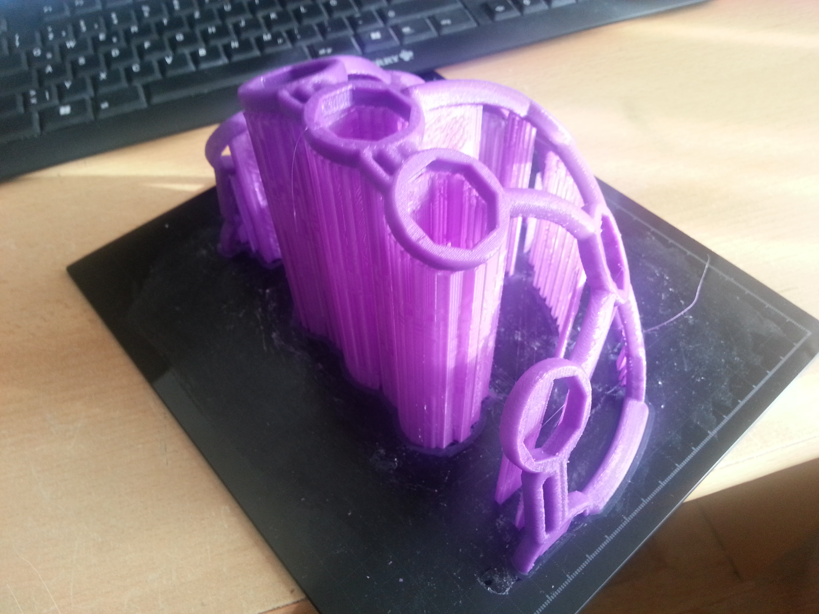
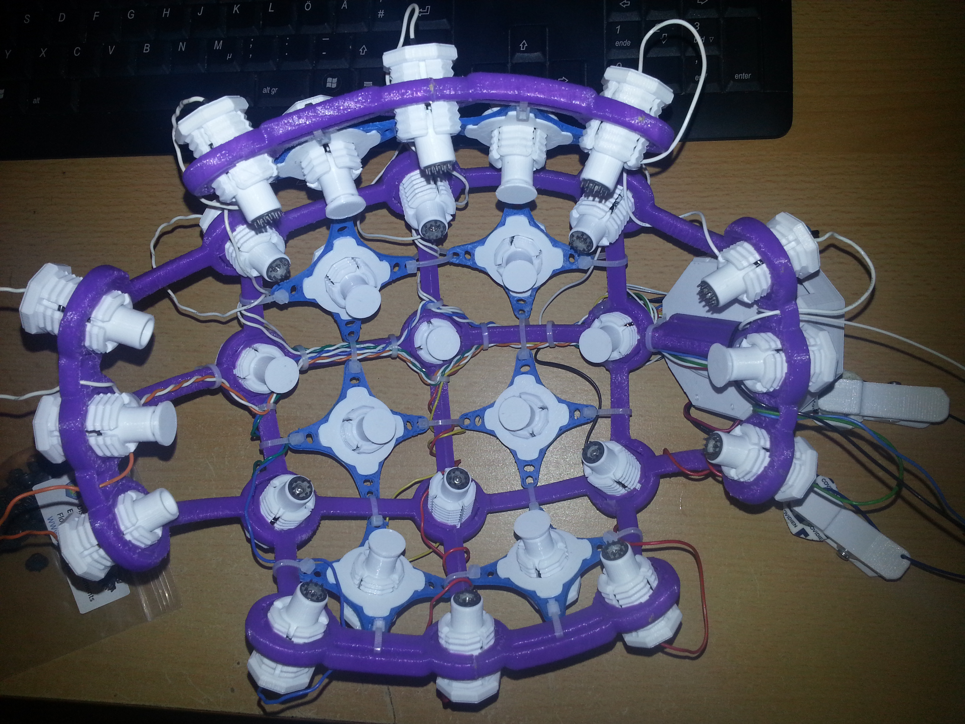
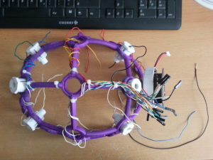
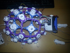
Time to print the headware (“Ultracortex Nova/Supernova”)

The print was done on an Ultimaker 2 clone with the recommended slicer settings and turned out ok. It took about 12 hours and I experienced some problems while printing the first half. Some parts snapped off because the print head collided with plastic that was bending up during cooldown. This happened only during a few layers of the print (approx after one third) because the structure was not stable enough at that stage. I could repair the broken parts by filling the defects with hot glue.  When printing the second half I had an eye on the process and coud prevent that from happening.

20160616_075440

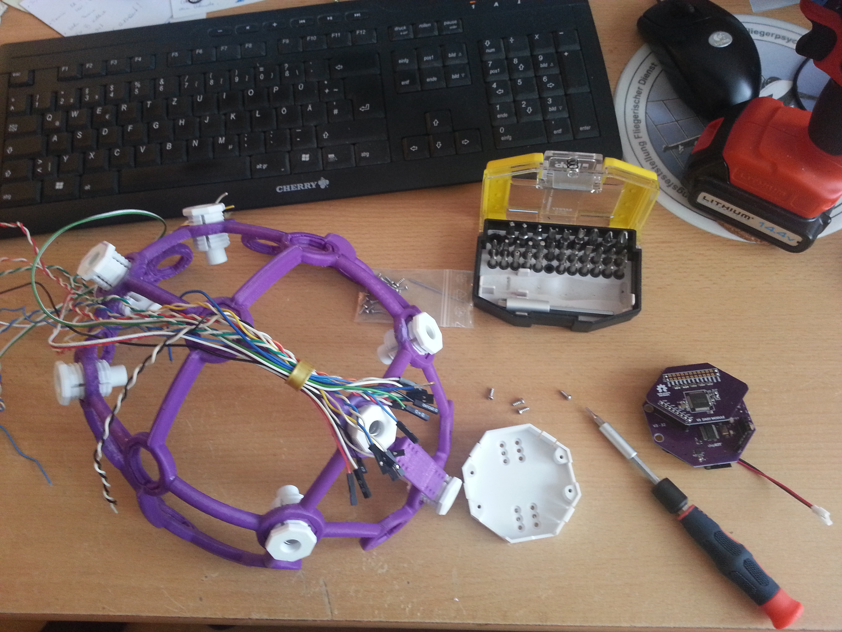
Used old PC tower cables to do the wiring. They were done in twisted pairs. All left electrodes are white and all right electrodes are colour-coded. That way you don’t need that many colors and nevertheless finding the corresponding electrode is easy.

20160617_103454

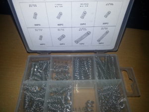
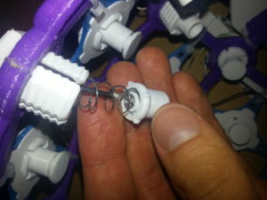
There are spring sets sold on the usual trading platform that contain the necessary springs to build the electrode inserts. The one below contains the “weak” as well as the “strong” spring for the “dummy inserts”. The weak spring had to be pulled apart a few mm to fit better.

20160701_092408

20160617_110640

20160617_145008

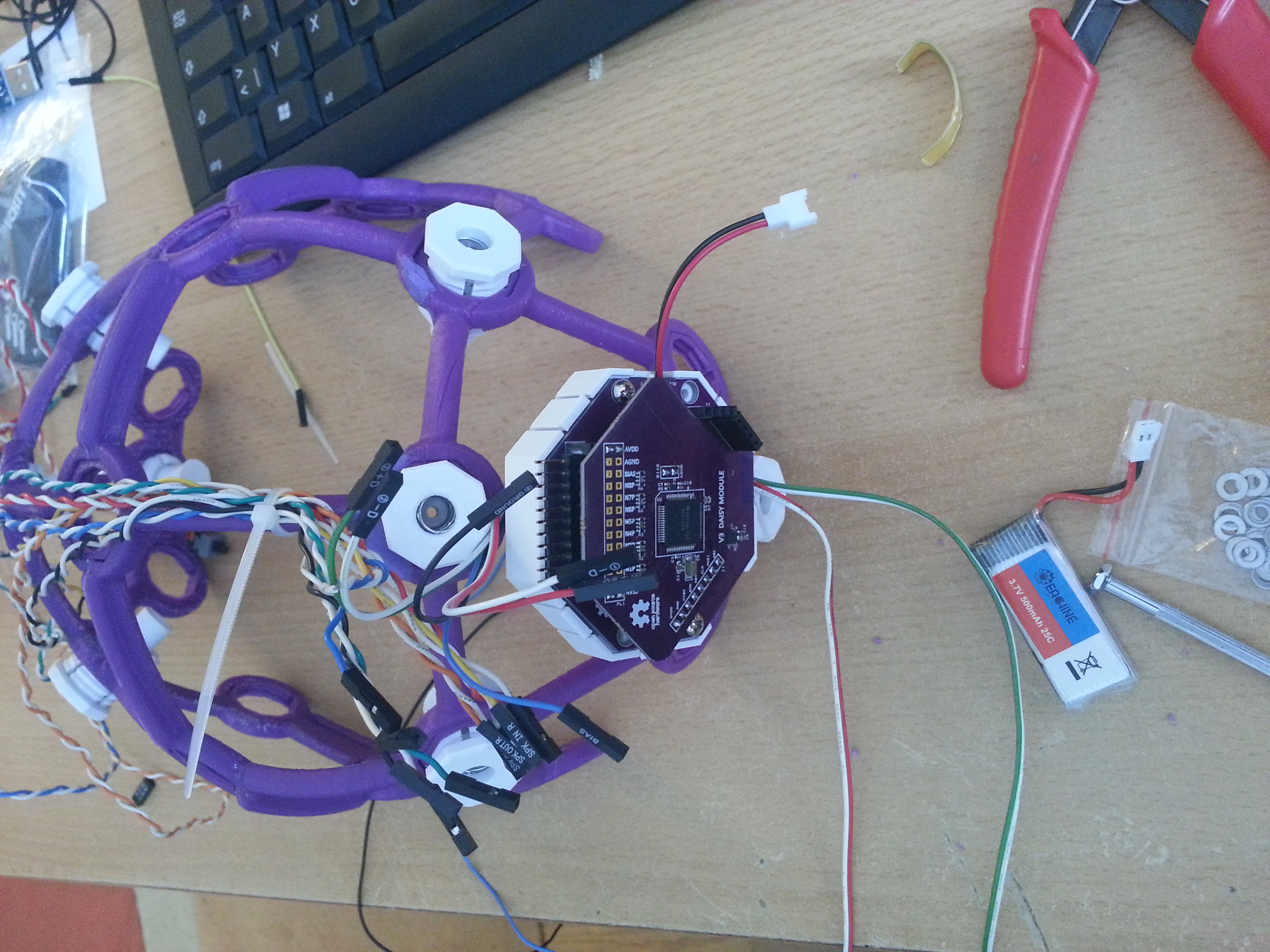
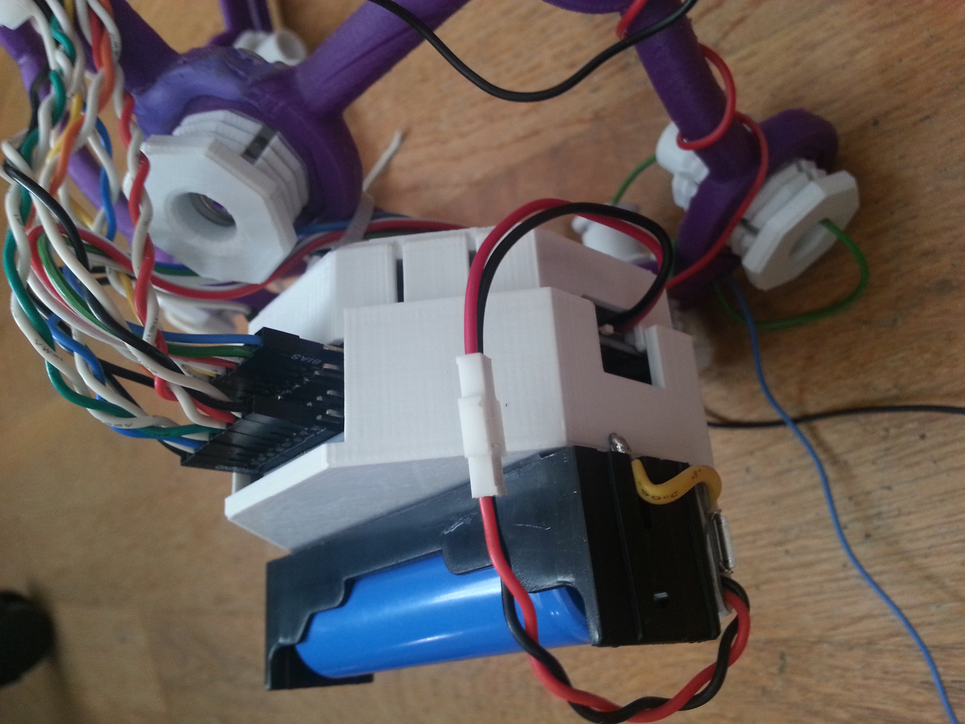
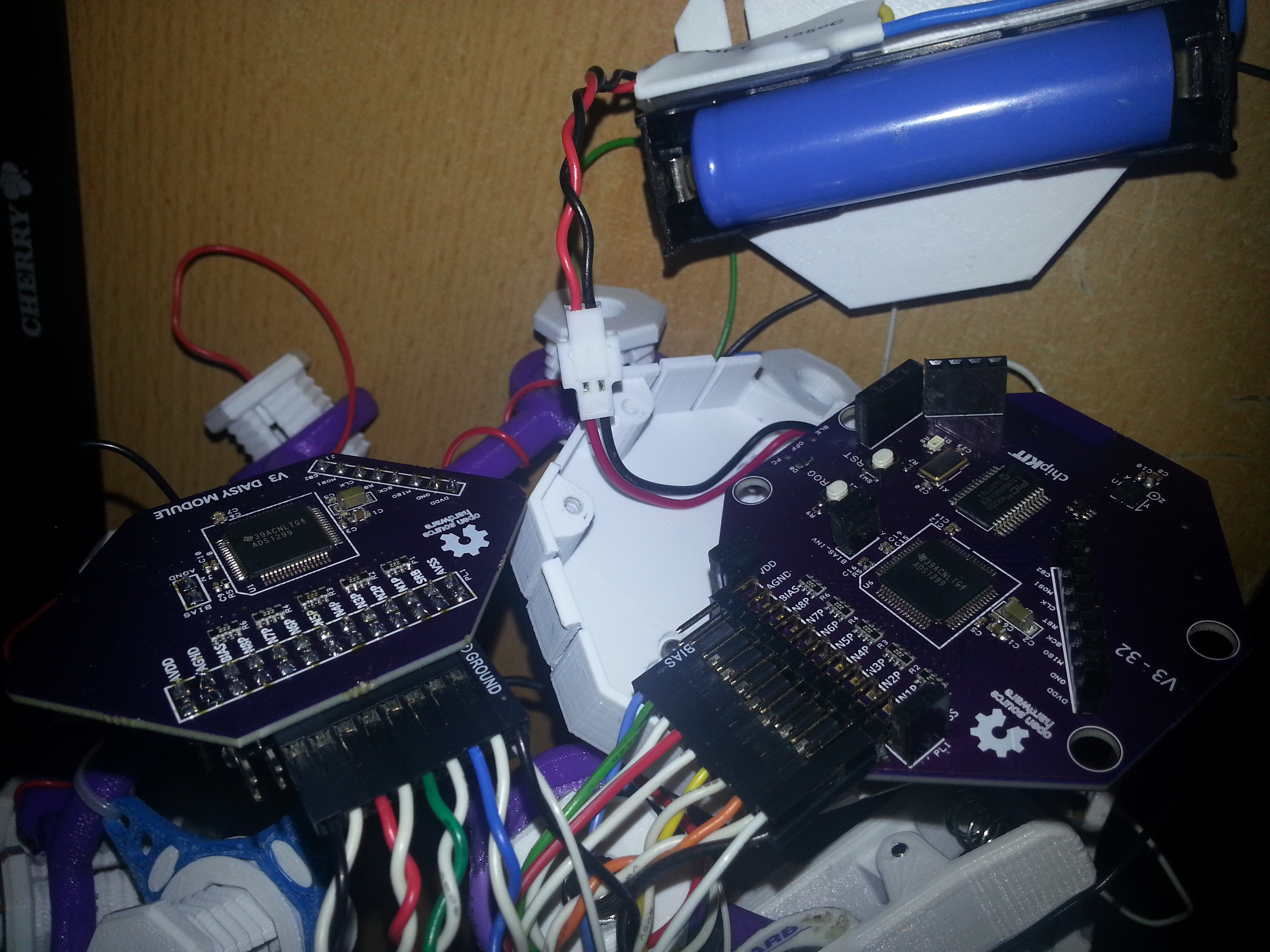
As you can see, I soldered the header of the Daisy board on the bottom side which takes up less space.

20160617_164954

OpenBCI parts <–this zip file contains my snap-on lid design that also covers the Daisy board as well as the earclip electrode design. Both parts can be found on Thingiverse as well:

http://www.thingiverse.com/thing:1635759

http://www.thingiverse.com/thing:1648317

20160620_080217

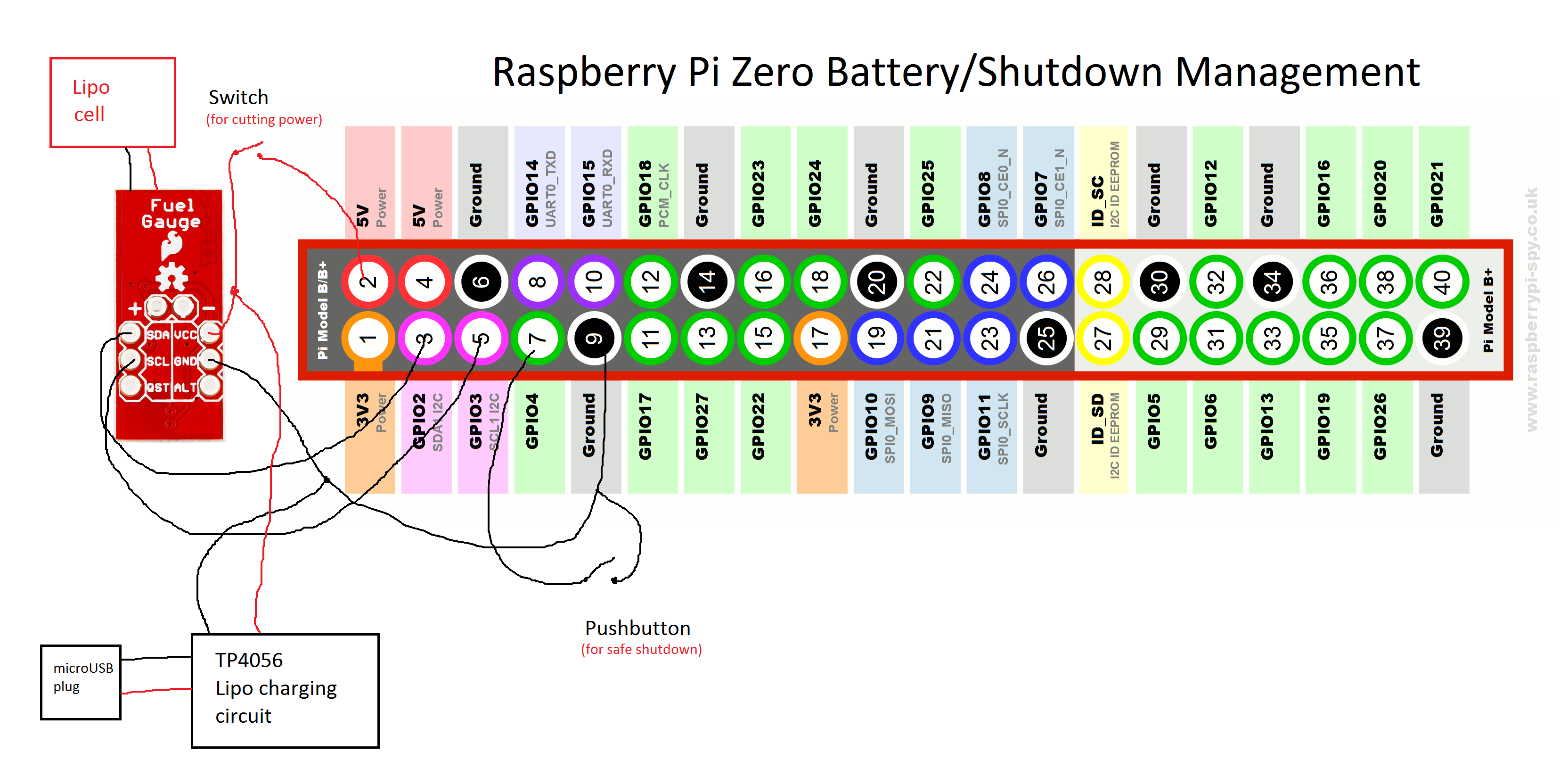
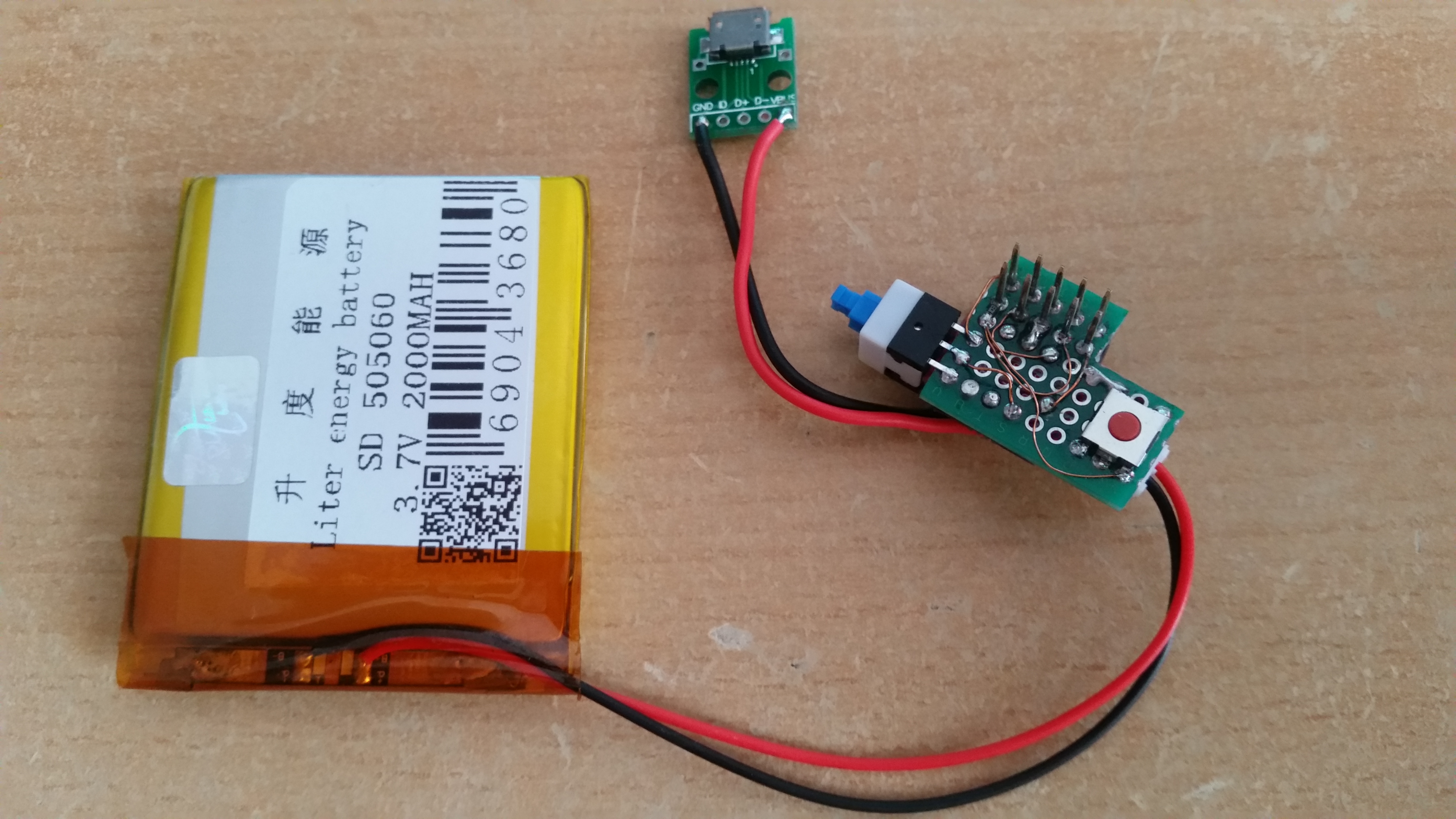
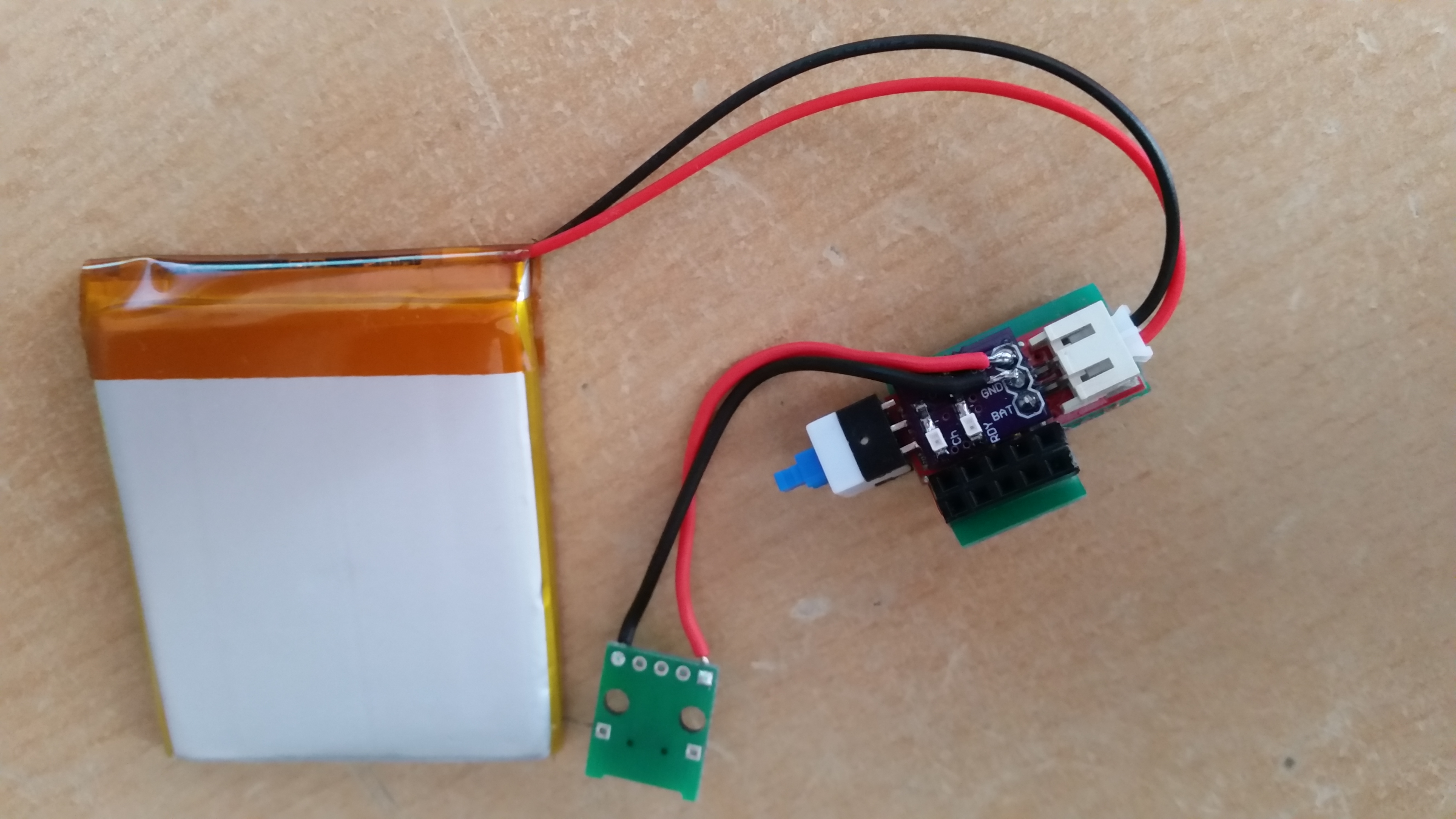
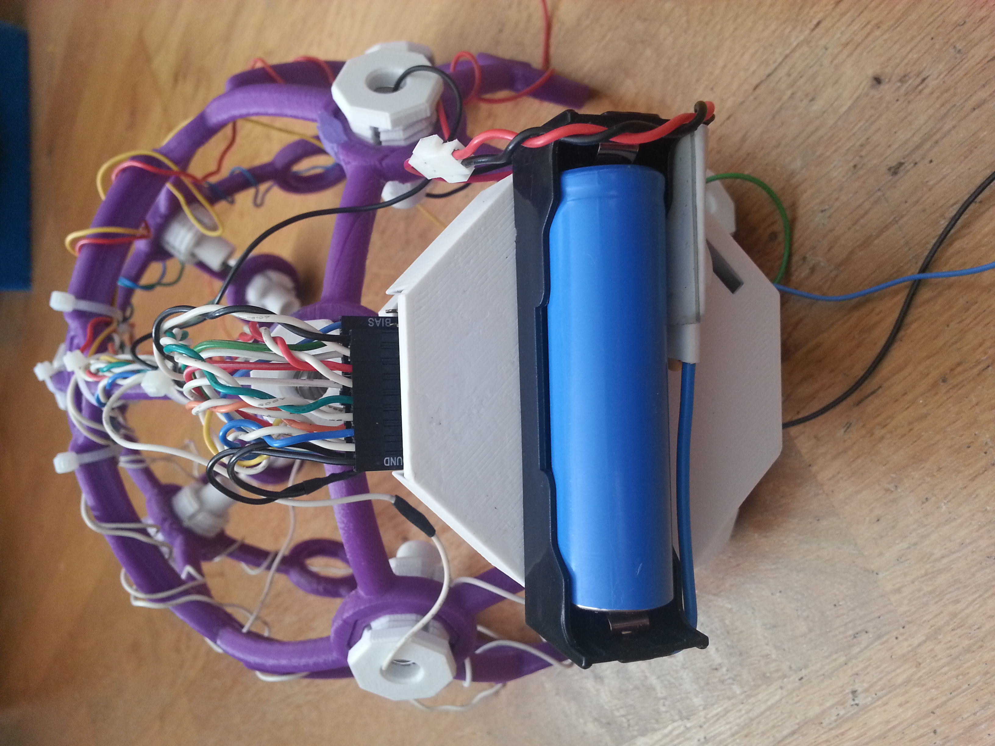
An 18650 holder with TP4056-based protection and charging circuit was placed on top to have a reliable power supply.

cover_on_daisy1

cover_on_daisy2

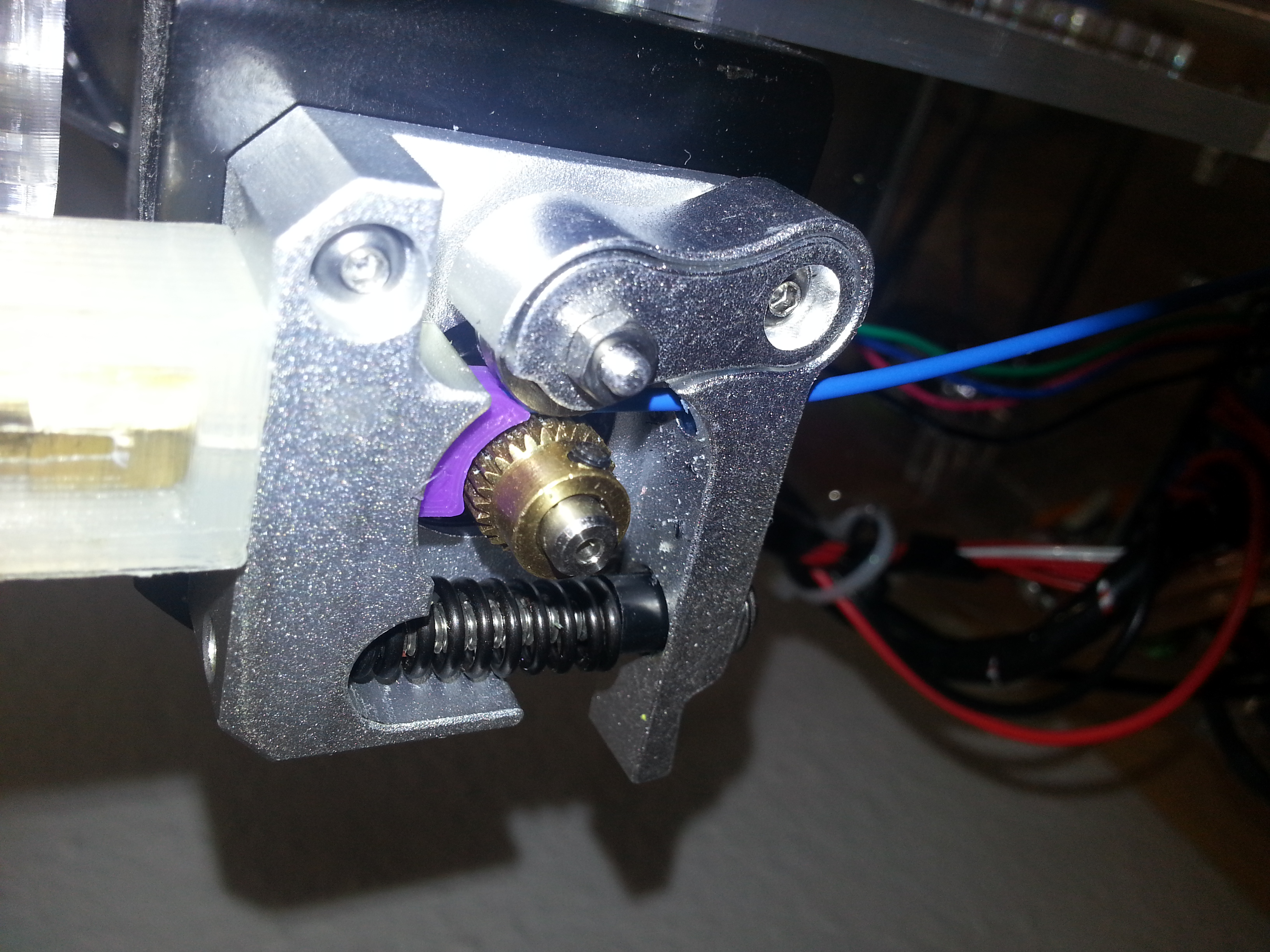
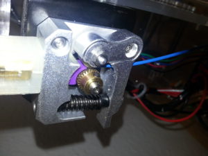
What you’re not being told: you have to print the “QUADSTAR” parts of the Ultracortex Nova/Supernova in PLA SOFT or any other elastomer filament. I had to modify my Prusa i3 extruder to prevent the soft 1.75 mm filament from kinking before entering into the bowden tube. This part fixes the issue: http://www.thingiverse.com/thing:1652091

Also I found that I had to turn off retractions because as soon as the filament passes the extruder drivewheel, it gets compressed and shoud not undergo this process twice because then it gets too damaged to be pushed into the bowden tube and extrusion simply stops at that point. Pain.

20160630_094022

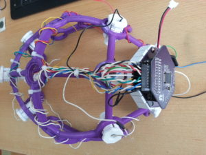
Finished Iron Maiden, err…. I mean Ultracortex, wired for the 16 channel standard configuration according to the Processing GUI with as many “comfy inserts” as possible.

20160630_195026

20160630_195049

20160630_201633

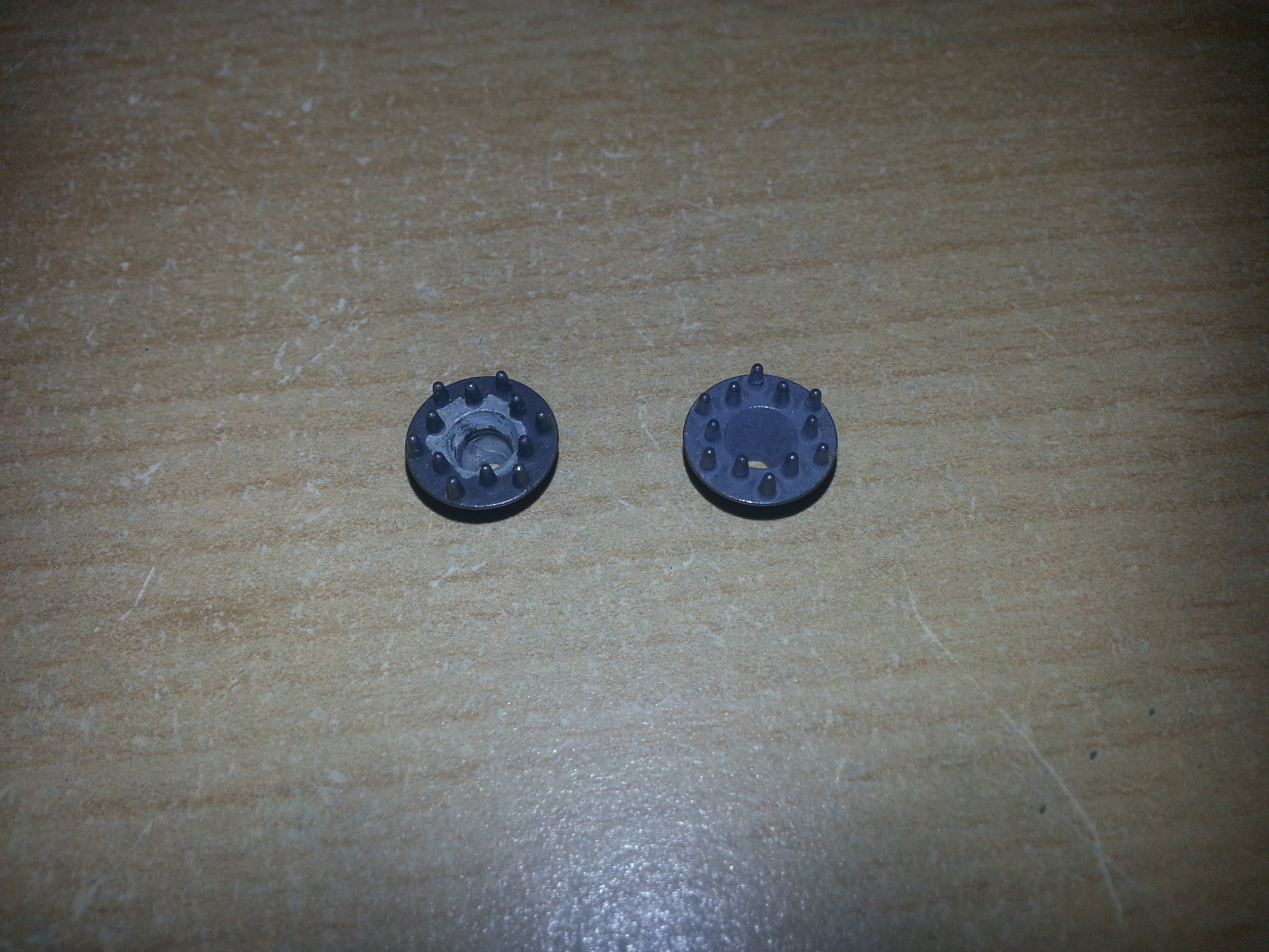
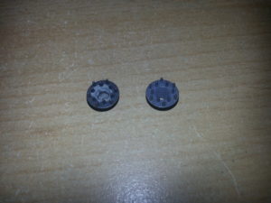
One thing I noticed after using the Disposable / Reusable Dry EEG Electrode [TDE-200] was instant corrosion. Not that surprising given that two different metals (stainless steel M2 bolt and Ag/AgCl surface) come in contact. As you can see on the picture below on the left electrode the AgCl layer corroded away to that extent after only one day. As a comparison there’s a fresh electrode on the right. The only solution I see at the moment is to attach the electrodes only if they are needed.

20160701_081452

A slight modification was done to be able to add/remove electrodes more quickly: the electrode cables were soldered directly to the M2 nuts and superglued to the back of the electrode holder, so the nut stays attached to the plastic part even if there is no bolt pressing it down.
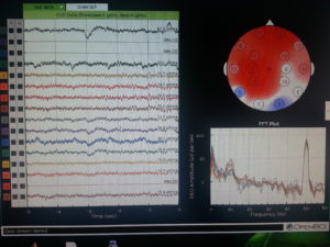
20160630_200402

Results:

Rocording with my eyes closed. Note the alpha peak in the FFT plot. As you can see not all channels are working. It’s not that easy getting 16 dry electrodes to work. I’m also having issues with channel 2 for some reason. Maybe there’s a bad solder joint somewhere on the PCB.

20160630_194627

Conclusions:

The OpenBCI V3 32bit + Daisy is a clean design and a good way to get 16 channels of electrophysiological data up and running and a great pplication for the ADS1299. The documentation is definitely good enough to build everything yourself, assuming you have some experience with SMT soldering. The DIY approach is also cheaper. I think you can get away with one third the price for the 32bit board and Daisy module, not including the cost of your labour of course. It’s a challenging project, but for me it was worth the effort. The DIY approach gives you the possibility to modify the design if you need to. I would like to use the potential of the ADS1299 more in the future and for example increase the sampling rate.
When it comes to the headware, my initial fascination faded a little when I discovered that the Ultracortex is quite painful to wear! The comb electrodes are no pleasure on your skin, let me tell you! But they do provide good signal quality almost instantaneously. The corrosion issue is also a significant one. I’m wondering how the signal quality changes as soon as the AgCl layer is gone completely. Maybe there’s a way of re-applying the layer by electrolysis in NaCl solution. This remains subject of further investigation. Other that those insights I find the design of the Ultracortex amazing! It’s a perfect example of great design specifically for 3D printing. Everything fits together perfectly well and looks great! Many thanks to the OpenBCI team for making their great work open source!


RFD22301 (RFduino) breakout

I’ve been doing some projects with the RFD22301, also known as RFduino and therefore decided to make a breakout for it. It’s also the radio used on the OpenBCI v3 system for data transfer, communication and programming. This breakout board can also be used as an OpenBCI dongle and can be plugged directly on this CP2102-based USB to TTL UART converter. Of course any other converter will do as long as it has 3.3V logic level. Watch out for that!


RfduinoBreakout


RFduinoBreakout


The jumper sets the DTR pin of the USB to serial converter to either the reset of the RFduino or its GPIO6. If it’s on “reset”, the RFduino itself is programmed during code upload. On the other position it starts programming the microcontroller on the OpenBCI board, assuming the OpenBCI firmware is flashed on the RFduinos of both the “Host” and the “Device” side.


Eagle files:
RFduinoBreakout

Arduino Pro Mini – nRF24l01+ 1.27mm adapter

The Atmega328P and nRF24l01+ combo is also a quite common thing to use over and over again in wireless sensor nodes, remote controls and so on.
I’ve chosen to make an adapter for the Arduino Pro Mini (the 3.3V version) to be able to piggyback small SMD versions of the nRF24l01+ with 1.27mm pad pitch on it. This way you have a tiny board sandwich which is not much bigger than the Pro Mini without the need of wiring everything up over and over again.

nRF24l01+ProMiniAdapter

NRF24l01_promini_adapter

A quite uncommon soldering technique is required to connect the adapter and the pro mini: align the holes of the pads of the Pro Mini and the adapter and after heating up the top pad, let the solder reflow to the bottom pad through the top pad. Of course you can solder headers as well. There is room on the board for a 0805 capacitor (0.1µF-10µF are sometimes used to prevent power issues while transmitting). The VCC and GND as well as the optional IRQ pins of the radio are broken out on solder pads and have to be wired manually, since I didn’t want to make the adapter too big and still leave some flexibility.

Eagle files:
NRF24proMini