Breakout boards for the HopeRF RFM23BP 433MHz modules with SMA connectors. Fabricated by the famous Magic Purple PCB Factory 😉
These modules come in different operating frequencies and are supposed to transmit with up to 1W. They communicate via SPI and need up to 600mA (max. output power). The power can be set in software. I made them for long range telemetry purposes, but will not operate them at full power, since a license is needed for output powers above 10mW, even in the free ISM (Industrial, Scientific and Medical) band.
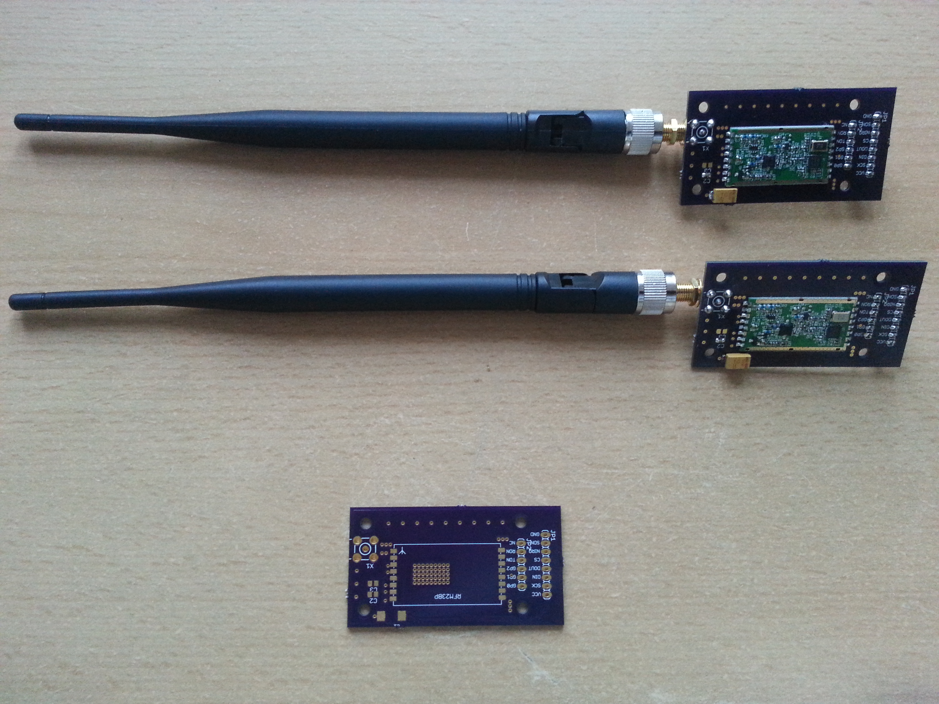
The modules have a blank ground plane without solder mask on the bottom side. A special soldering technique was used here: I tinned this blank area and filled all those vias on the breakout board with solder. Then I applied flux to both the module and the board and finally soldered them together by holding the sandwich against my cooking plate. This will make perfect heat dissipation from the power transistor.

Eagle board files:
RFM23BP
Monthly Archives: June 2014
Quadrotor
using the Hobbyking control board or Multi Wii Platform and a Futaba FASST System.
ESCs: Turnigy Plush 18A
Motors: EMAX CF2822
Propellers: 10×4.5”
I will upload some self-explanatory pictures of the construction process:


LM3406 LED Driver Board
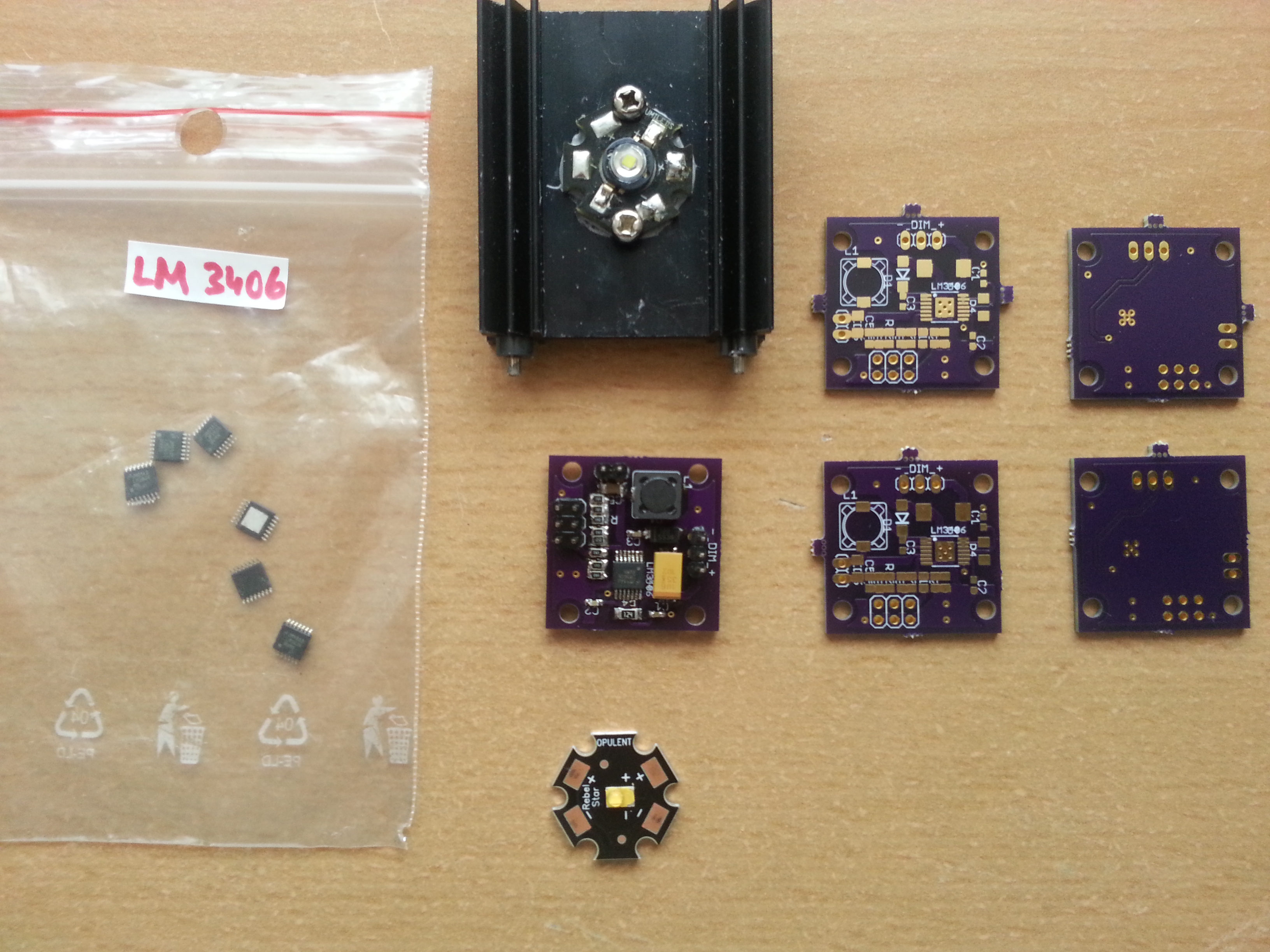
I was given a bunch of LM3406 1.5A switching buck converter led driver chips for evaluation purposes the other day. These chips make very powerful and efficient LED/laser diode drivers when used properly.
In order to make them useful a PCB had to be designed again, because the TSSOP14 package is too fine-pitched to prototype on a perfboard (as opposed to SOIC8). So I made an adjustable version with selectable output currents and had it manufactured by OSH Park.
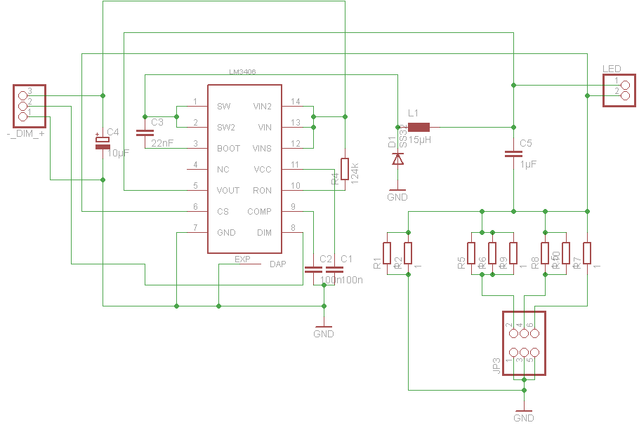
The trick behind the current adjustment is to have several sense resistors in parallel out of which certain ones can be added to or removed from the circuit via jumpers. The board is pretty versatile since you can add the appropriate resistors for currents you need and parallel them up if you are not able to find the right values. You don’t need to populate the entire row of resistors when a single fixed LED current is needed. Check out the data sheet for more information on sense resistor values.
In my current configuration you can select 300mA (no jumper), 700mA (only jumper in the middle populated) and 1000mA (all jumpers populated) and also some more exotic settings if you combine the jumpers differently.
Eagle board files:
LM3406 led driver
Arduino Scales
While browsing some adafruit pages I came across this one.
I thought it would probably be useful to have completely hackable scales for some future project or just for household use and so I adapted the hardware frome the above tutorial.
Since I was only able to find the SMD version of the INA125 I had to make a PCB again, but this is not my first DIY PCB, so the process was pretty easy.
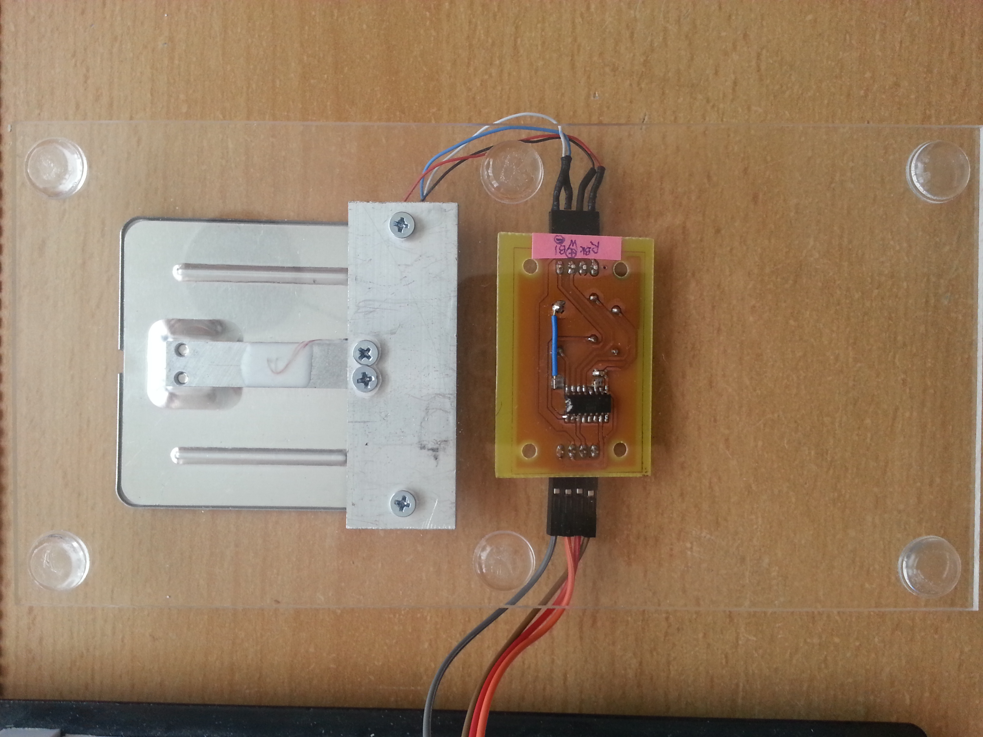
If you are looking for small load cells on ebay or similar shops, you will probably figure out that a cheap mini scales (around 4€) is even cheaper than a single load cell of comparable size (5€). This is why I purchased the complete device rated for up to 1 kg and disassembled it. Prior to taking it apart I measured the weight of some small household items to use them as calibration weights later on in the calibration process. The second advantage you have when getting complete scales is the flat and stable platform mounted on the load cell for you so you don’t have to do it yourself.
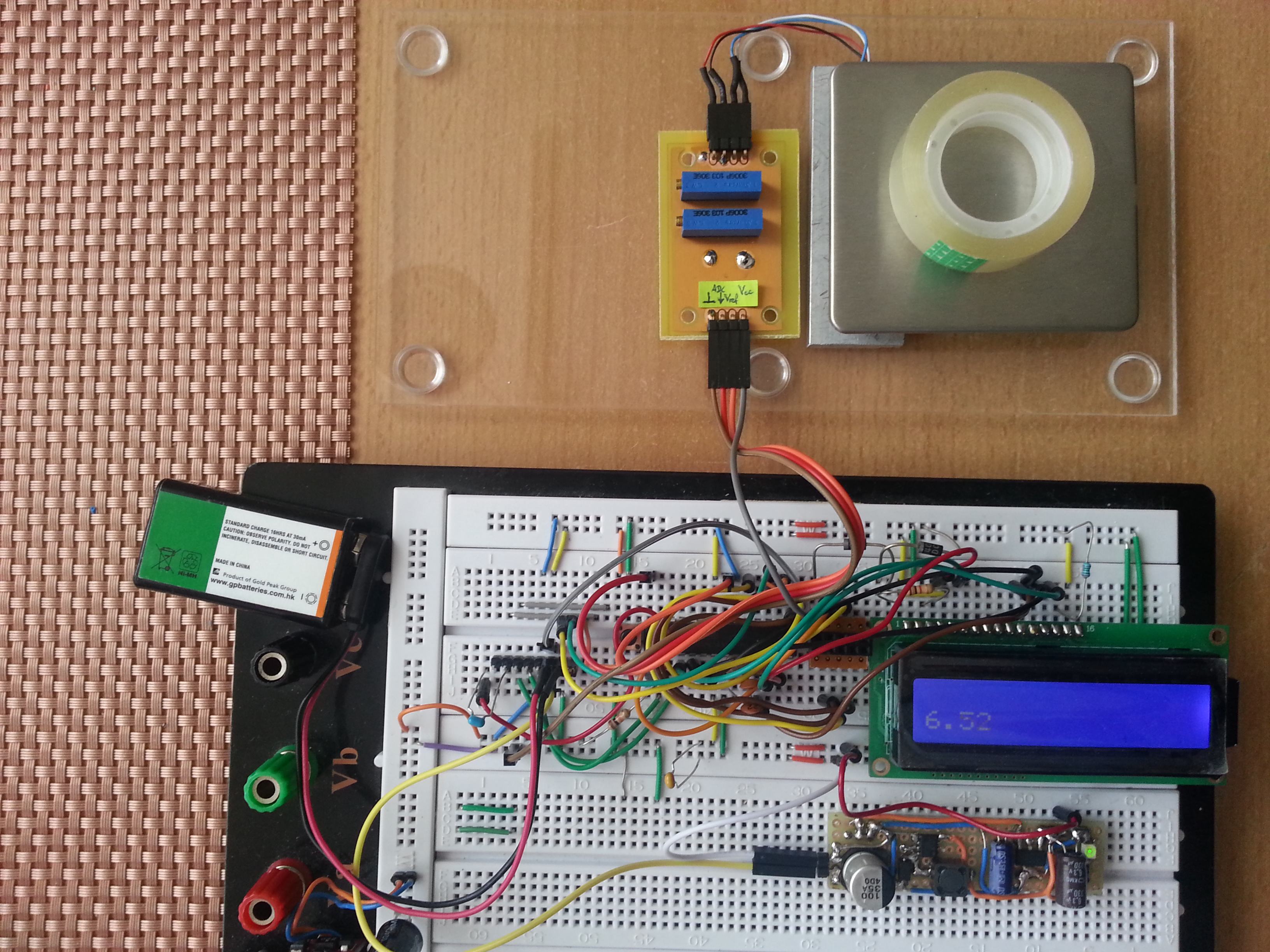
Here’s the complete scales on a breadboard. For wiring of the analog part with the microcontroller check the tutorial above.
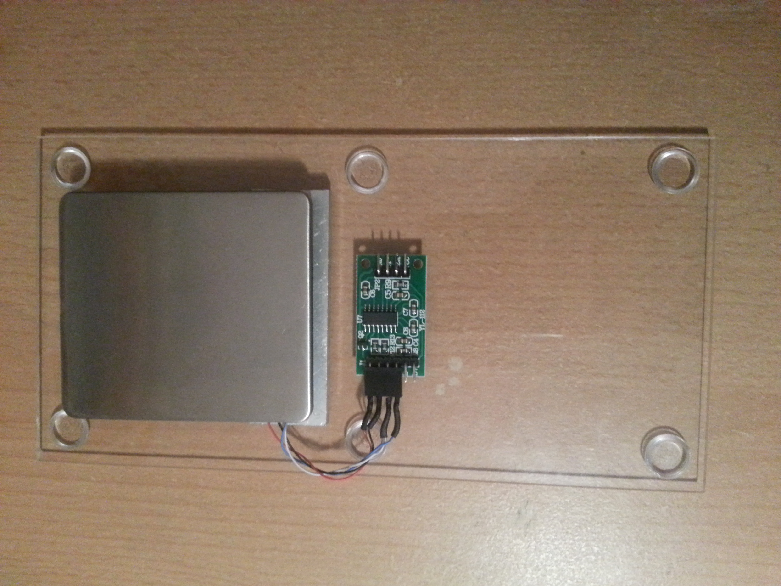
The load cell was mounted to an acrylic plate with a piece of aluminum in between for stable weight distribution.
Here’s the schematics and the board file for the SMD INA125 (as always in eagle format):
Load Cell Amplifier
Update: After finding the HX711 breakout board on ebay I upgraded the scales board to this interesting part. It’s a 24 bit ADC that can communicate to a microcontroller over a synchronous serial protocol. It is specifically designed to amplify signals from load cells and gives you a higher resolution (0.1 g). Several Arduino libraries for this chip are around.
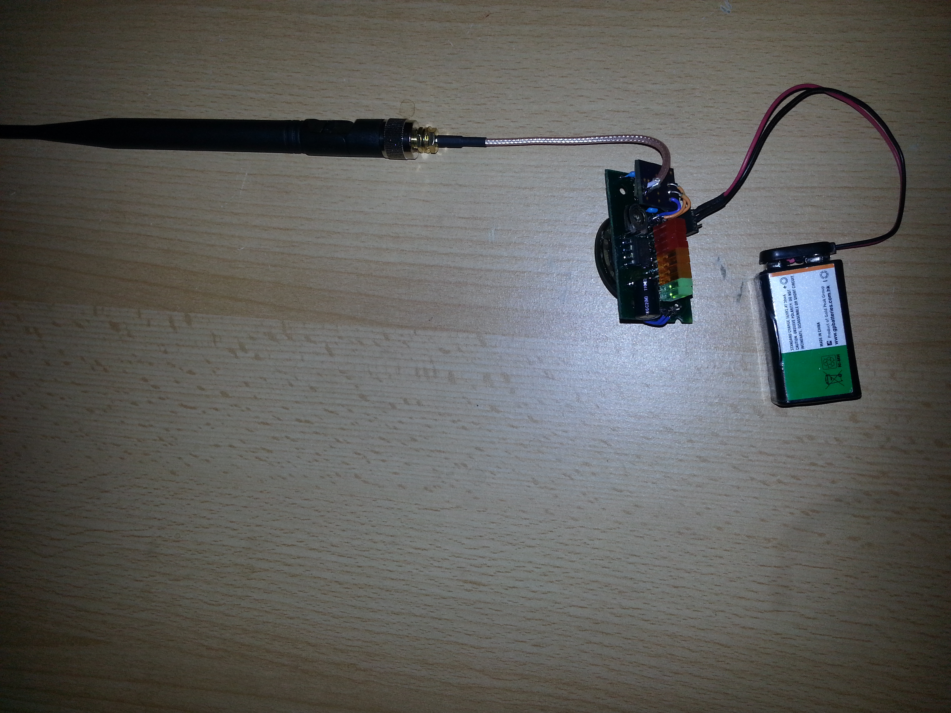
RF Detector 50MHz-3GHz
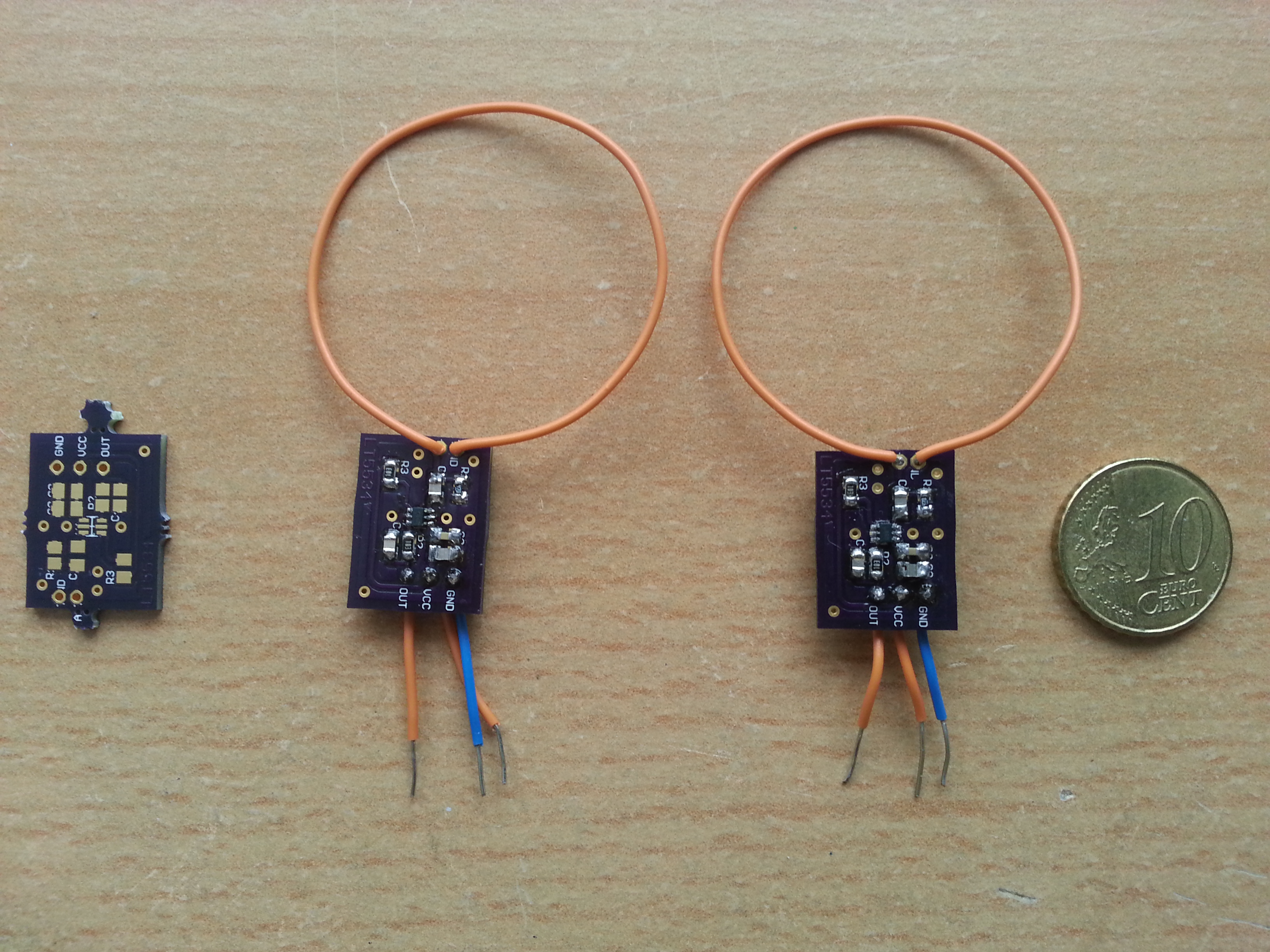
When working with RF modules that transmit/receive in the 2.4GHz or whatever range it’s sometimes useful to have some means to detect whether transmission really takes place. This wideband RF detector based on the LT5534 by Linear Technology is capable of doing so. Moreover it can tell, how strong the signal is, since its output ranges from 0V to VCC (5V in this case) and is proportional do the dBm of the received signal. The chip can be for free, which is what I did. The idea for this project as well as the first carrier board design was originally from Laboratory for Experimental Computer Science
at the Academy of Media Arts Cologne.
I improved the board a little and ordered some PCBs from OSH Park It takes about 2 weeks for them to arrive in Germany and costs almost nothing, since the boards, like the chip itself are tiny. Apart from the LT5534 itself the carrier board uses few standard components.
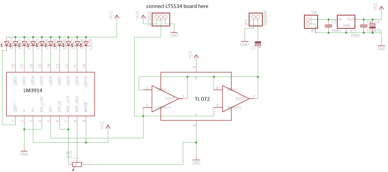
To have an audiovisual output I decided to add a LM3914-based bar graph meter and a speaker with a TL072 opamp buffer, since I had both of them lying around luckily. I added the buffer because the LT5534’s output cannot deliver enough current to drive the speaker’s membrane adequately. What you hear is the raw modulation of the incoming RF signals. It’s like getting a 6th sense for the invisible RF pollution around you. For example if you hear periodic knocking sounds, it’s probably from a WiFi router.
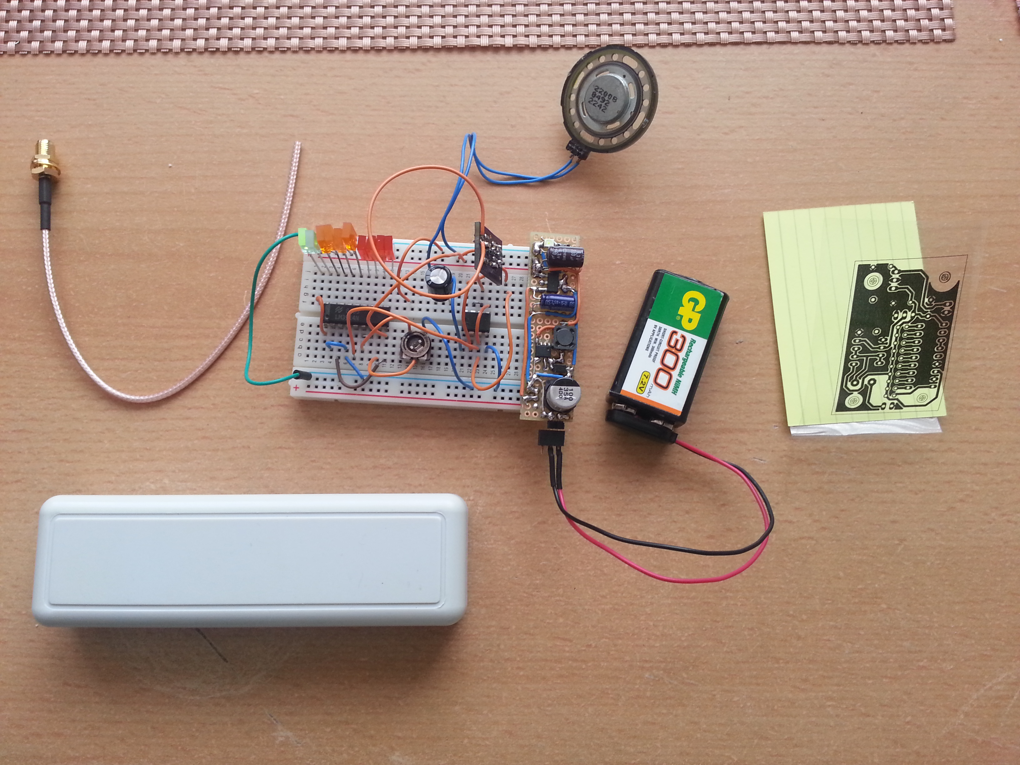
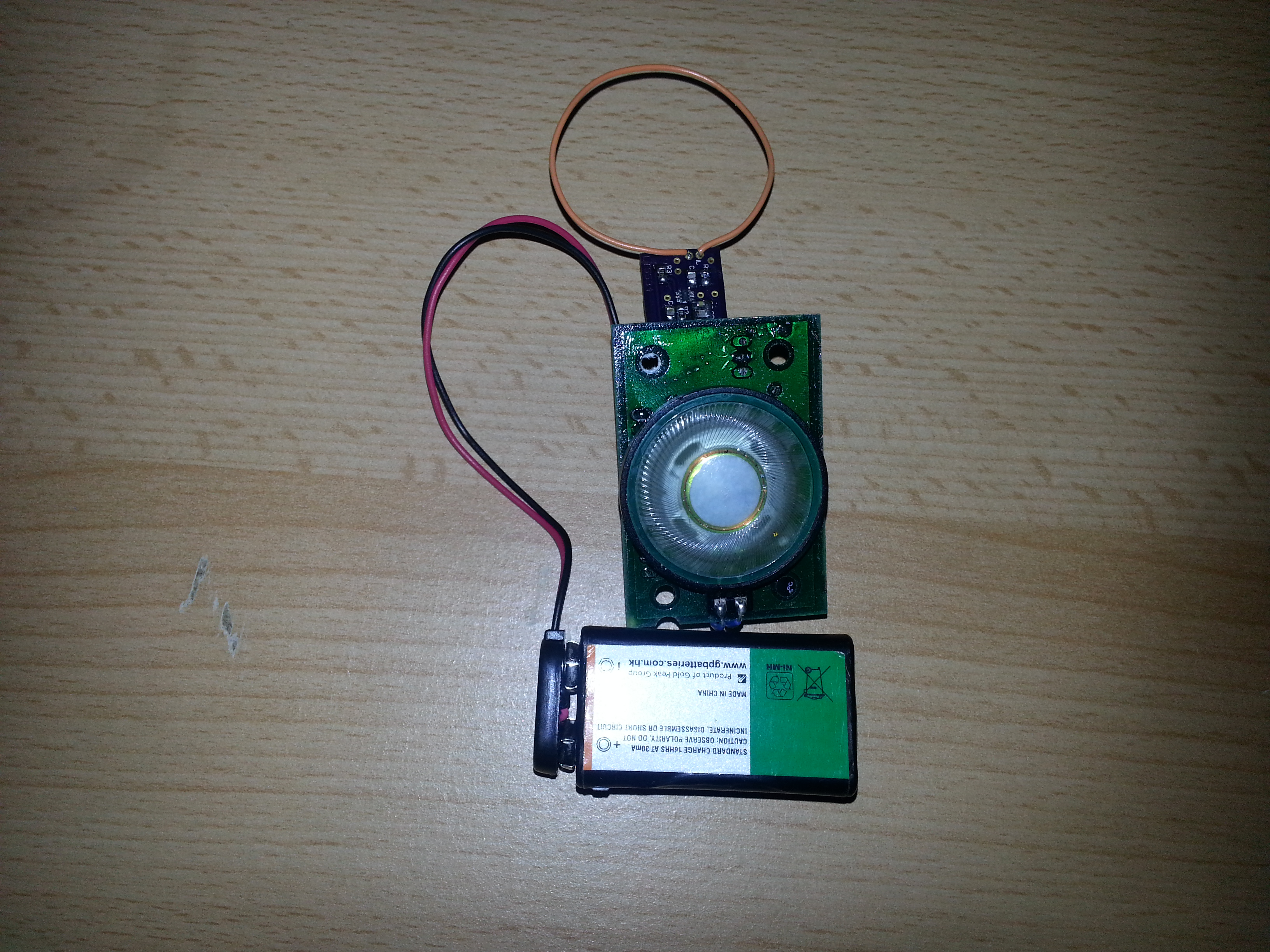
Here’s the preliminary breadboard version of the ciruit. The loop antenna was made for 2.4GHz but the device still receives signals over a pretty wide RF band. The PCB was designed specifically for the depicted enclosure. The carrier board will be connected to the bar graph board. The loop antenna will be replaced with a SMA jack with a coax cable pigtail to have the possibility to connect different antennas for different frequency ranges.
DIY PCB ready to be built into the project box:
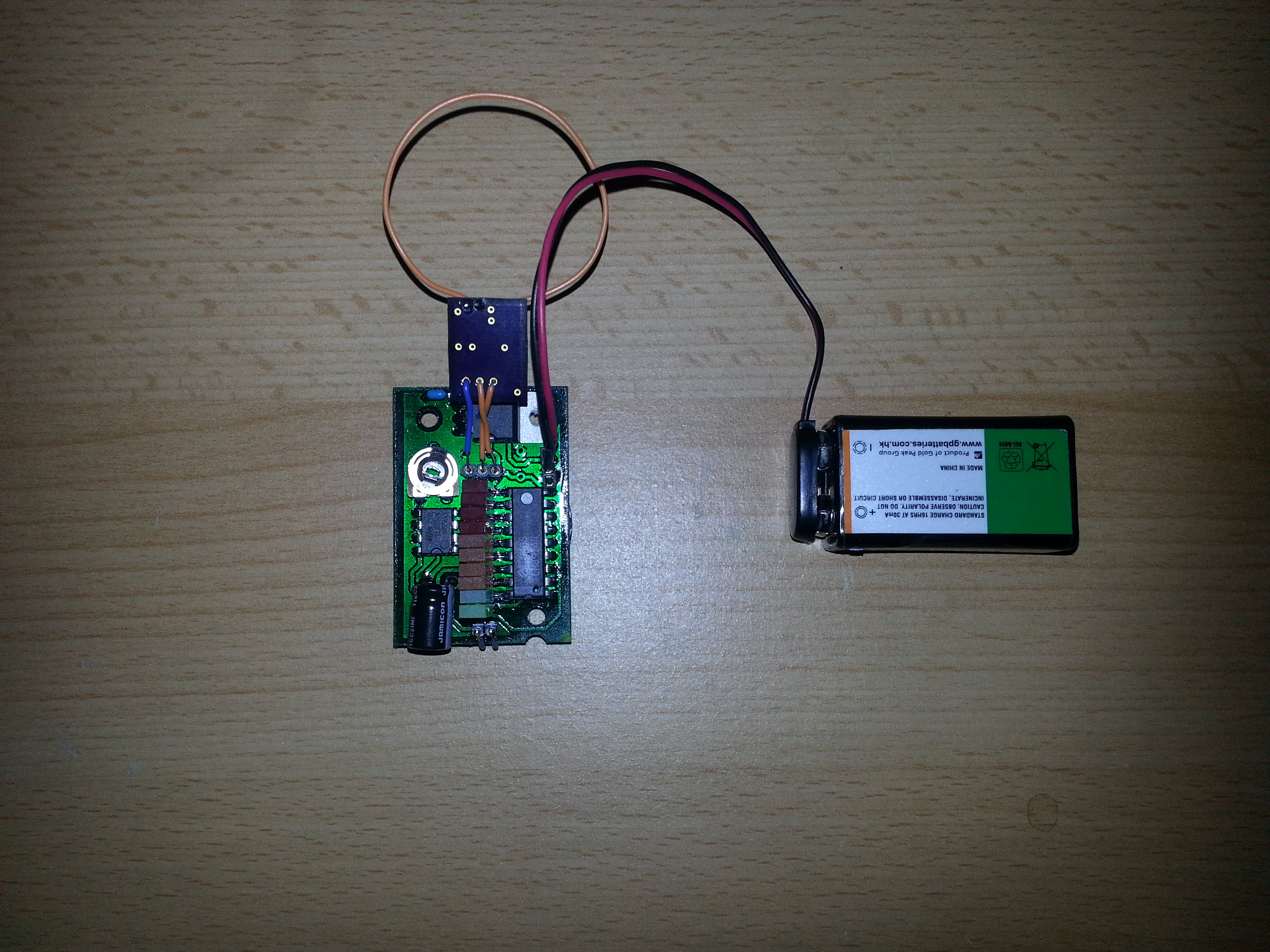
Now with loop antenna removed and SMA jack attached via coax pigtail.
Here are the modified schmatics and board files for the LT5534 carrier board:
LT5534 rf detector
Here is the board file and schematic for the bar graph and audio amplifier:
LM3914 rf signal strenth meter
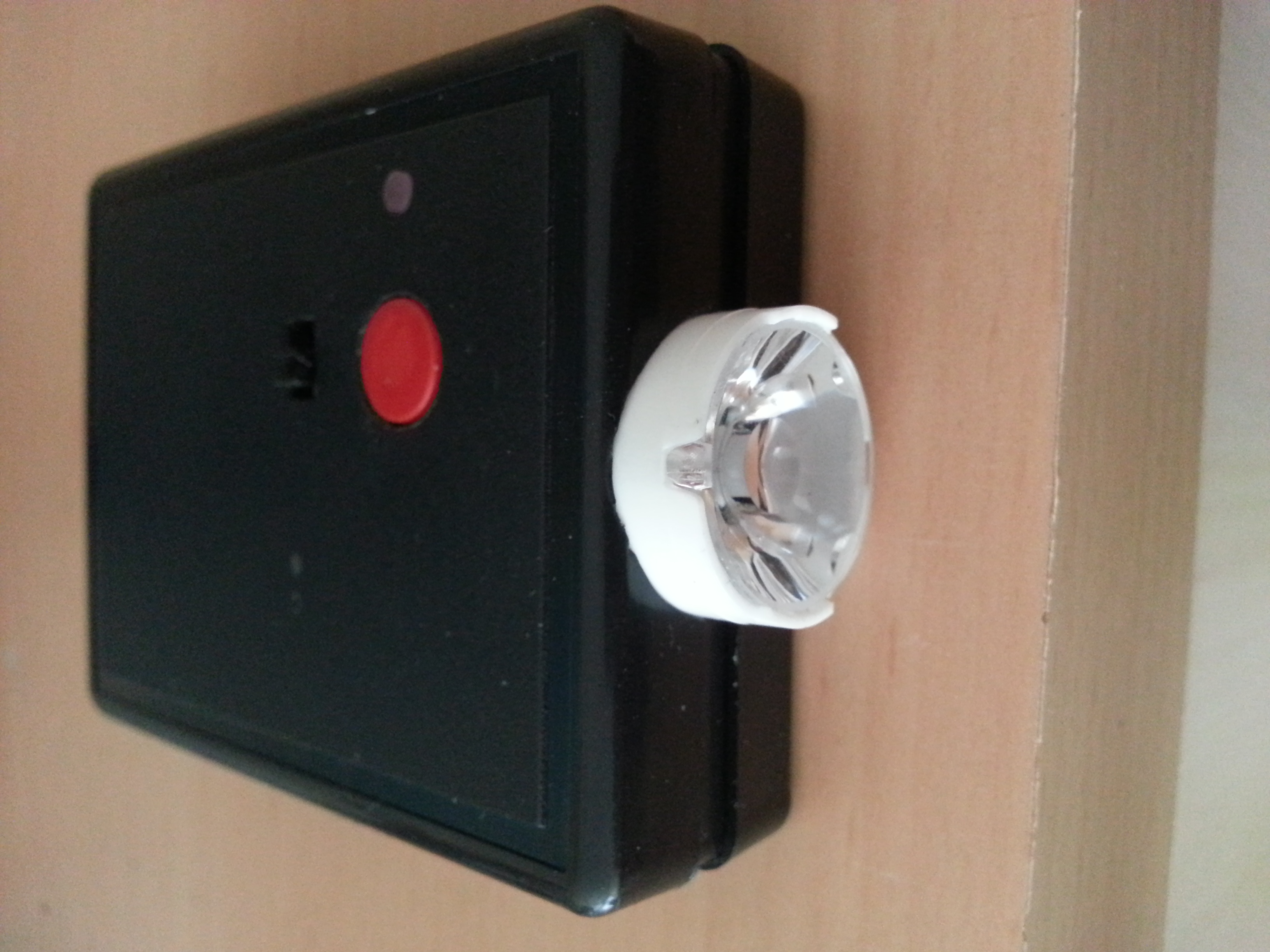
TV-B-Gone Deluxe
TV-B-Gone clone with LiPo battery charger and 1W infrared LED


1W Diode Laser And Synthetic Felt
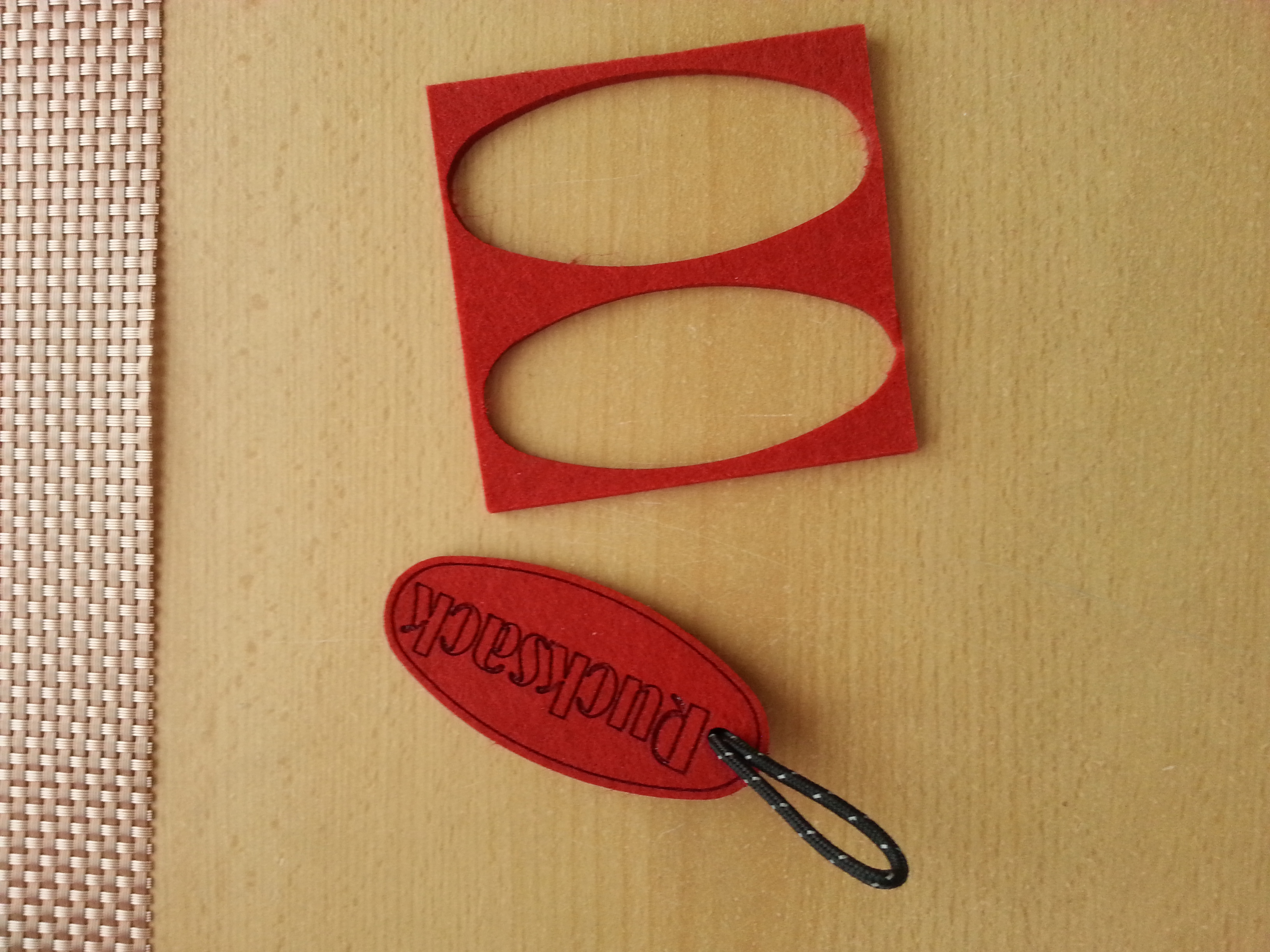
Beverage coasters out of synthetic felt are well-suited for cutting and engraving with the diode laser. They can be bought in hobby stores.
Fast feed rates engrave, whereas slow feed rates cut. It’s as simple as that. The design is drawn in Inkscape.
Arduino-Android Telnet Interface
Arduino-Android CC3000 Wifi chip-based Telnet Interface
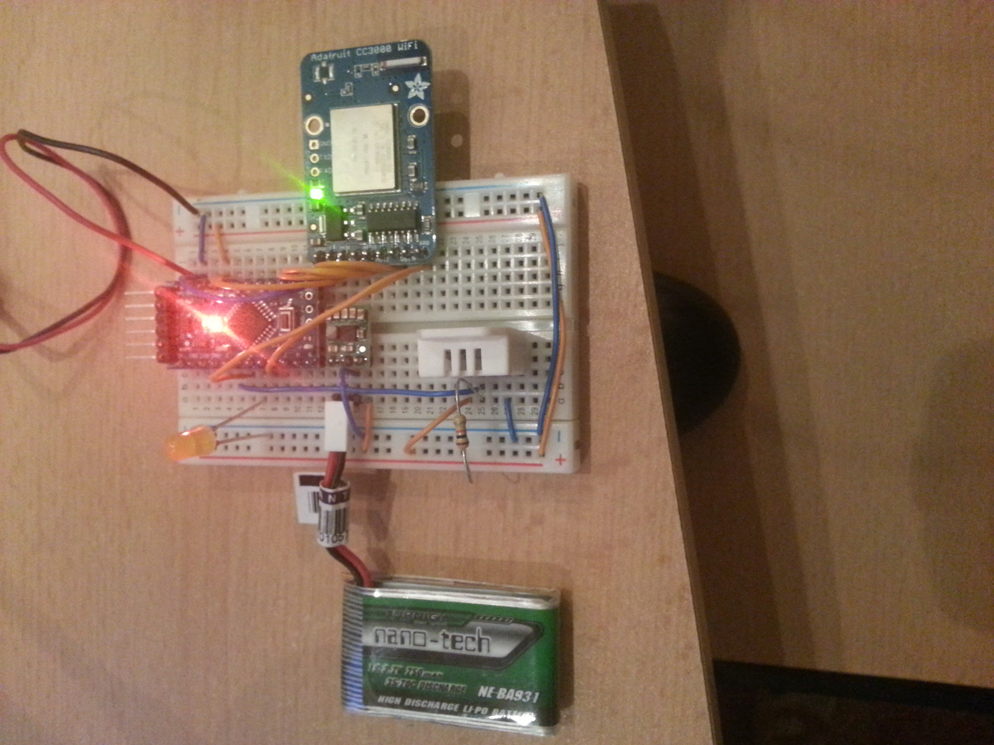
This page provides some guidance on how to set up a wifi connection between an Android device and a minimalistic arduino-based server. The wifi chip used in this project is the CC3000.
Tutorials on how to get the CC3000 to work with the Arduino are all over the WWW, what I would like to add is an example on how to have the Arduino talk to a smartphone or similar.
The communication protocol used here is Telnet. The data comes from a DHT22 sensor which measures humidity and temperature. Actually this is an extended mashup of the open home automation and the candy bowl project. The Android App uses client sockets to communicate to the arduino, which operates in server mode.
Android App Code (ADT Eclipse project):
TelnetClient
Arduino Code:
CC3000_Telnet_server_DHT22
Simple ECG/EEG/EMG amplifier
I’ve been experimenting with electrophysiology for some time and therefore the need to better understand the amplifier circuitry arose. I sampled some INA321 instrumentation amplifiers from Texas Instruments and started experimenting. After soldering them to a breakout board you can breadboard them.
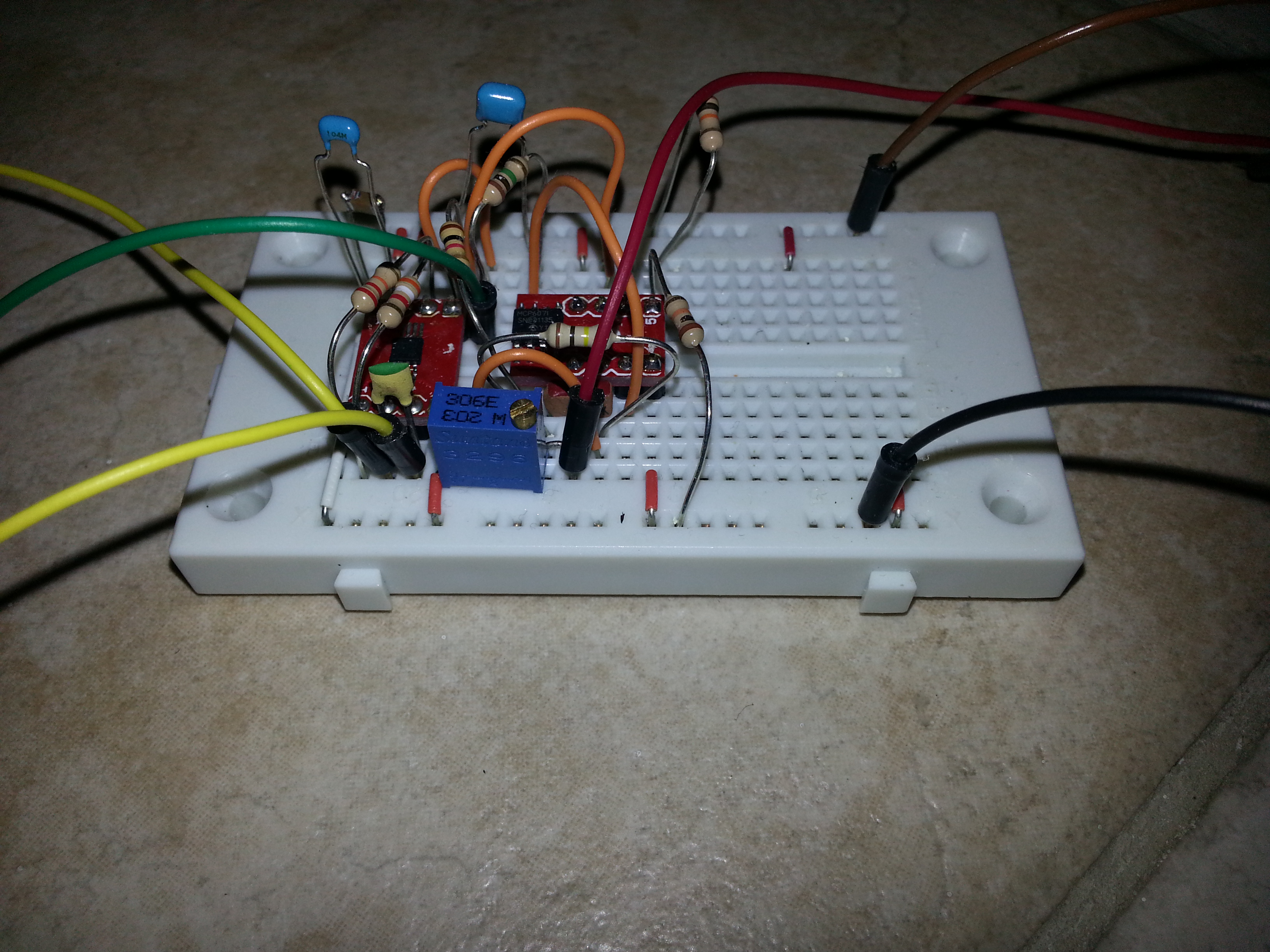
The simple setup below can readily be attached to an analog to digital converter of a microcontroller and to 3 skin electrodes wherever you like to attach them 😉
Besides the instrumentation amp (chip on the left) only one additional dual low-noise opamp is used, which implements a buffer for reference voltage and a bessel filter for reducing mains line interference.
Eagle schmatic:
simplestEEG
Jumbo I2C 4-Digit LED Display
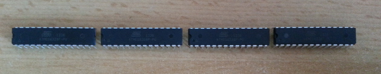
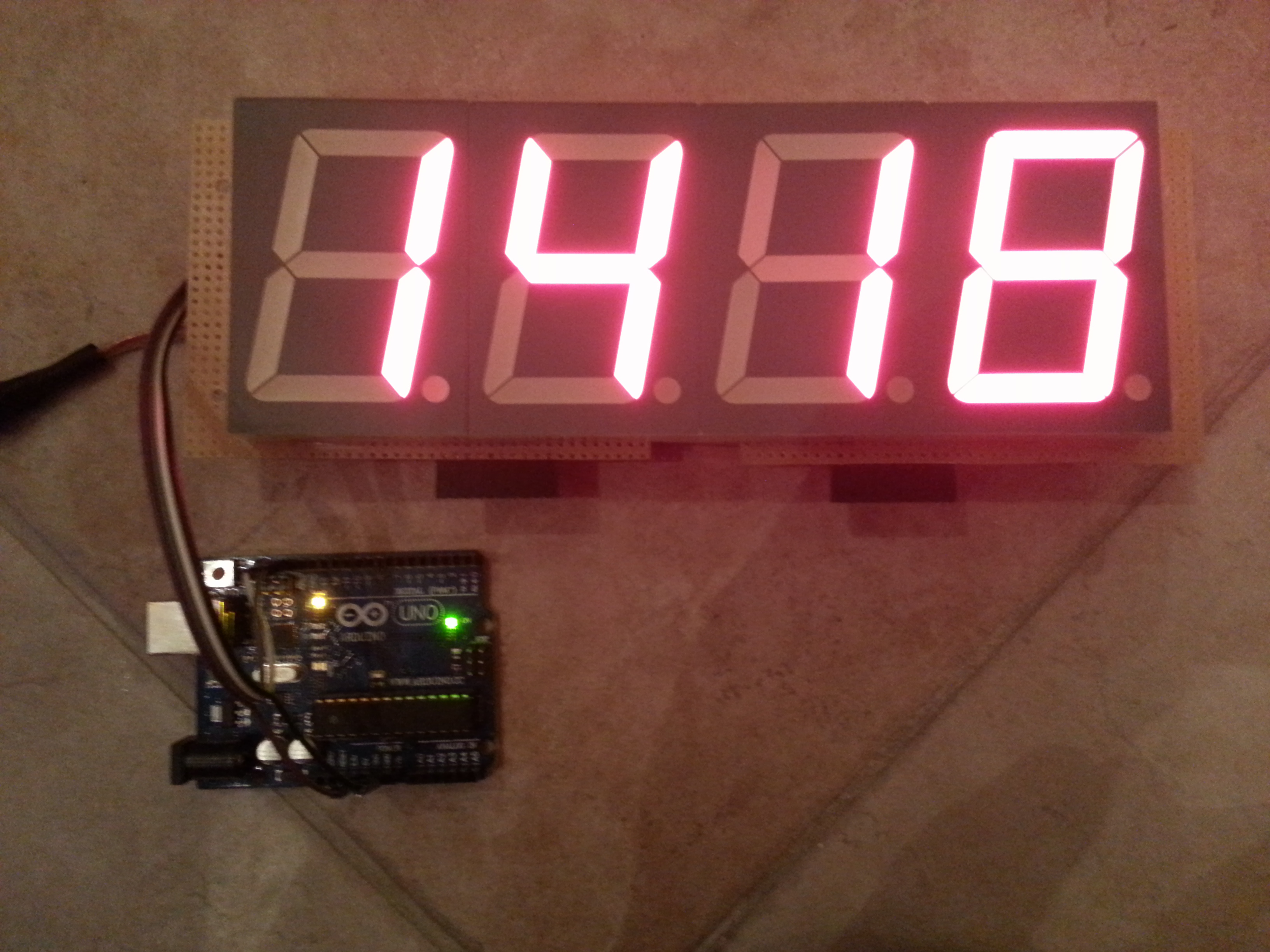
This is a huge 4-digit i2c display based on an Atmega8 @16MHz which operates as a i2c slave and does all the multiplexing via timer interrupt. The display is composed of four sa23-12srwa seven segment displays (common anode) with a digit height of 57mm. The firmware for the Atmega8 was written in AVR Studio in C.
It can be addressed simply connecting it to an Arduino and using the wire library. Whenever an ultra-readable bright digit display is needed that is easy to use, this one might come in handy. Some projects I thought of were an oldschool thermometer clock or a distance-measuring device for the garage entrance.
The anodes are driven using an ADN2981 driver and are attached to PB0…3. The cathodes take up the entire PORT D and are driven by a ULN2803. Those drivers are necessary, since the segments (except for the decimal point) are several red LEDs connected in series dropping ca. 7.4V. One does not simply connect one of those to a blank microcontroller port.
Source code for the Atmega8 (AVR Studio, C) as well as the Arduino which acts as a I2C master:
I2CjumboDisplayFirmware
// Functions to talk to the DIY jumbo LED four digit display board


#include <Wire.h>

void setup()
{
  Wire.begin(); // join i2c bus (address optional for master)
}


void loop()
{
  for(int i = 0; i < 10000; i++){
    ledDisplayInt(i);
    delay(30);
  }
}

void ledDisplayInt(int number){
  int number_disass = number;
  int Digit_X000, Digit_0X00, Digit_00X0, Digit_000X;
  Digit_X000 = number_disass/1000;
  number_disass %= 1000;
  Digit_0X00 = number_disass/100;
  number_disass %= 100;
  Digit_00X0 = number_disass/10;
  number_disass %= 10;
  Digit_000X = number_disass;
  Wire.beginTransmission(40); // transmit to device #40 for some reason it addresses a slave with the address 0x50
  //Wire.write("x is ");        // sends five bytes
  Wire.write(byte(0));  //begin
  //sending 0...9 displays the digit, sending 10 makes digit dark
  if(number > 999){
    Wire.write(Digit_X000);              //thousands
  }
  else{
    Wire.write(10);
  }
  if(number > 99){
    Wire.write(Digit_0X00);                //hundreds
  }
  else{
    Wire.write(10);
  }
  if(number > 9){
    Wire.write(Digit_00X0);                //tens
  }
  else{
    Wire.write(10);
  }
  Wire.write(Digit_000X);                //ones
  Wire.write(4);                //decimal point position (0...3, 4 is no comma)
  Wire.write(1);                //display on/off (0x00 => off)
  Wire.endTransmission();    // stop transmitting
}