Specs:
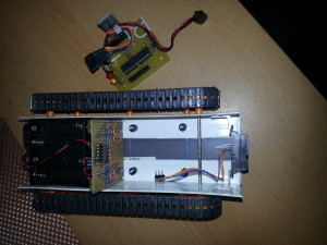
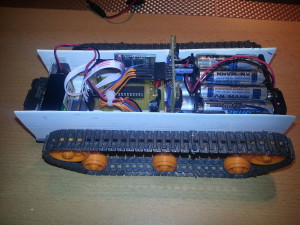
Tamya dual motor gear box
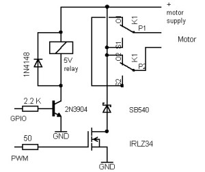
dual homebrew relay-based H-Bridge
controlled by a Atmega328p with Arduino UNO Bootloader.
Sharp GP2D120XJ00F distance sensor (range: 10-80cm)
el-cheapo Bluetooth module (HC-06)/Xbee Series 2 modules


This little project just continues growing. All circuits are built on perfboards, mostly using discrete components. The Arduino components are really bearbones and make a great base for further development, as the basic functions such as movement and obstacle detection are already worky nicely.
I’ve added a “ceiling” on top, which is a blank perfboard for now. Anything can be mounted/soldered to it, for example a 2.4 GHz wireless camera with moving mechanics+electronics. For programming you have to connect an FTDI breakout board/cable.
The H-Bridge is a quite simple design. Only 2 MCU pins are needed for speed control and reverse in direction. As for now, the device is working with 2 separate power supplies: 4 AA cells for the motors and a 9V battery for the “brain”/wireless camera. This is not really elegant, but it was the simplest way of eliminating the noise caused by the DC motors.

Here’s the dude in motion. Pretty fast and stable …
This is the stationary mode (if you just turn it on, but don’t send it any commands yet): it has got a character of its own 😉 It rotates for a random time period, which makes its behaviour quite unpredictable, yet wirelessly controllable with the current firmware.
The Arduino code and the corresponding Android app (created with the MIT App Inventor) can be found under the download link below. The app is somewhat universal, since it sends ASCII characters when a button is pressed, but its most useful feature is its bluetooth management functions, which supports pretty much all baud rates.
Tamya Robot
Another modification I’ve done on this robot is adding a thumb-joystick-controlled X-Bee-based remote control. Since this mod was only a temporary breadboard hack, I don’t remember the connection details but they were pretty simple and can be read out of the code.
Transmitter code:
//Robot controller TX part: analog joystick on A4 and A5
//Xbee module connected to TX and RX of the Arduino
int left_PWM, right_PWM, dir = 0;
int fb = 0;
int lr = 0;

void setup(){
  Serial.begin(57600);
}

void loop(){
  fb = analogRead(A4);
  lr = analogRead(A5);
  right_PWM = 0;
  left_PWM = 0;

if(fb > 530){      //back
    dir = 1;
    fb=map(fb,1023,530,255,0);

    if(lr < 480){
      lr = map(lr,480,0,0,255);
      left_PWM = fb - lr;
      right_PWM = fb;

    } else if(lr > 520){
      lr = map(lr,520,1023,0,255);

      left_PWM = fb;
      right_PWM = fb - lr;
    } else {
      left_PWM = fb;
      right_PWM = fb;
    }
}else if(fb < 490){    //forward
    dir=0;
    fb=map(fb,0,490,255,0);

    if(lr < 480){
      lr = map(lr,480,0,0,255);
      left_PWM = fb - lr;
      right_PWM = fb;
    }else if(lr > 520){
      lr = map(lr,520,1023,0,255);
      left_PWM = fb ;
      right_PWM = fb- lr;
    }else{
      left_PWM = fb;
      right_PWM = fb;
    }
} else if(lr < 480){    //only left track activated
    lr = map(lr,480,0,0,255);
    left_PWM = 0;
    right_PWM = lr;
    dir = 0;
 }else if(lr > 520){    //only right track activated
    lr = map(lr,520,1023,0,255);
    left_PWM = lr ;
    right_PWM = 0;
    dir = 0;
  }else {
    left_PWM = 0;
    right_PWM = 0;
    dir = 0;
}

//create string and send
String dataString = String(dir);
dataString += ',';
dataString += left_PWM;
dataString += ',';
dataString += right_PWM;
dataString += '\n';
Serial.print(dataString);

//delay to recover
delay(100);
}
Robot code:
//Robot Thumb Joystick Remote Control Sketch
//X-Bee module connected to TX and RX of the Atmega328
//Vehicle code: receives the strings via serial from the Xbee module and controls the
//power mosfets on left/right c_pins via PWM to drive the tracks

const int sensorPin = A0;       // SHARP Sensor

const int left_dir_pin = 4;     // all the motor pins
const int left_c_pin = 5;
const int right_dir_pin = 7;
const int right_c_pin = 6;

const int led = 13;              //green LED on SCK (digital pin 13)

int sensorValue = 0;    // variable to store the value coming from the sensor

unsigned int sensor_threshold = 200;
String inString = "";    // string to hold input
int currentNumber = 0;  //counter for value indices
int dir, left_PWM, right_PWM = 0;  //values read from the received String
//---------------------------------------------------------------------------
void setup()
{
  // declare the motor pins and led-pin as an OUTPUT:
  pinMode(left_dir_pin, OUTPUT);
  pinMode(left_c_pin, OUTPUT);
  pinMode(right_dir_pin, OUTPUT);
  pinMode(right_c_pin, OUTPUT);
  pinMode(led, OUTPUT);
  //zigbee-modem-baud rate
  Serial.begin(57600);
}
//----------------------------------------------------------------------------
void loop()
{
   int inChar;

  // Read serial input:
  if (Serial.available() > 0) {
    inChar = Serial.read();
  }

  if (isDigit(inChar)) {
    // convert the incoming byte to a char
    // and add it to the string:
    inString += (char)inChar;
  }

  // if you get a comma, convert to a number,
  // set the appropriate value, and increment
  // the counter:
  if (inChar == ',') {
    // do something different for each value of currentNumber:
    switch (currentNumber) {
    case 0:    // 0 = direction
      dir = inString.toInt();
      // clear the string for new input:
      inString = "";
      break;
    case 1:    // 1 = left:
      left_PWM = inString.toInt();
      // clear the string for new input:
      inString = "";
      break;
    }
    currentNumber++;
  }
  if (inChar == '\n') {
    right_PWM = inString.toInt();

  digitalWrite(left_dir_pin, dir);  //if 0, tank goes forward
  digitalWrite(right_dir_pin, dir);
  analogWrite(left_c_pin, left_PWM);   //PWM
  analogWrite(right_c_pin, right_PWM);
  // clear the string for new input:
    inString = "";
    // reset the color counter:
    currentNumber = 0;
  }

}
