
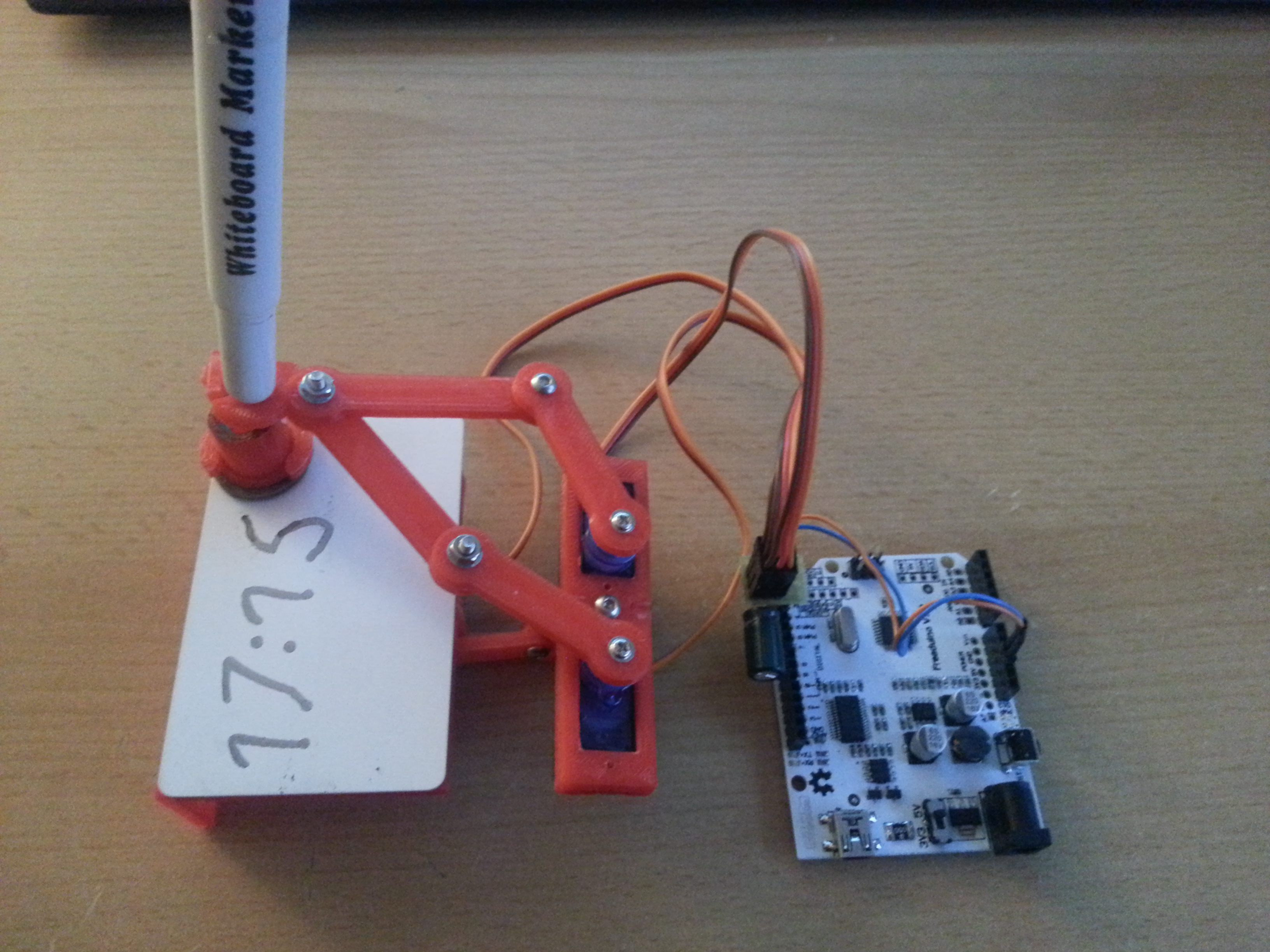
I’ve printed the parts for a Plot Clock in PLA and assembled it in a pretty much standard configuration, which worked great. Quite a bit of filing and sanding was necessary, but it was worth it, the final device was quite easy to calibrate. The only thing I found was missing is time keeping capability, so I added a DS1307 I2C real time clock module, which is a straightforward procedure. Learn how to set up the RTC HERE.
Before you run the sketch that sets the time on the RTC, make sure to remove the battery once to reset the DS1307. Put the battery back in and run the sketch. My modification on the Plot Clock code simply fetches the time once every time you power the arduino up. Further timekeeping is done by the ATmega.
// Plotclock
// cc - by Johannes Heberlein 2014
// v 1.01
// thingiverse.com/joo   wiki.fablab-nuernberg.de

// units: mm; microseconds; radians
// origin: bottom left of drawing surface

// time library see http://playground.arduino.cc/Code/time

// Date and time functions using a DS1307 RTC connected via I2C and Wire lib

    #include <Wire.h>
    #include "RTClib.h"

    RTC_DS1307 RTC;

// delete or mark the next line as comment when done with calibration
//#define CALIBRATION

// When in calibration mode, adjust the following factor until the servos move exactly 90 degrees
#define SERVOFAKTOR 555

// Zero-position of left and right servo
// When in calibration mode, adjust the NULL-values so that the servo arms are at all times parallel
// either to the X or Y axis
#define SERVOLEFTNULL 2075
#define SERVORIGHTNULL 1065

#define SERVOPINLIFT  2
#define SERVOPINLEFT  3
#define SERVOPINRIGHT 4

// lift positions of lifting servo
#define LIFT0 1350 // on drawing surface
#define LIFT1 1180// between numbers
#define LIFT2 850  // going towards sweeper

// speed of liftimg arm, higher is slower
#define LIFTSPEED 1500

// length of arms
#define L1 35
#define L2 55.1
#define L3 13.2


// origin points of left and right servo
#define O1X 22
#define O1Y -25
#define O2X 47
#define O2Y -25


#include <Time.h> // see http://playground.arduino.cc/Code/time
#include <Servo.h>

int servoLift = 1500;

Servo servo1;  //
Servo servo2;  //
Servo servo3;  //

volatile double lastX = 75;
volatile double lastY = 47.5;

int last_min = 0;

void setup()
{

  Wire.begin();
  RTC.begin();
  DateTime now = RTC.now();
  // Set current time only the first to values, hh,mm are needed
  int rhour = now.hour();
  int rminute = now.minute();
  setTime(rhour,rminute,0,0,0,0);

  drawTo(75.2, 47);
  lift(0);
  servo1.attach(SERVOPINLIFT);  //  lifting servo
  servo2.attach(SERVOPINLEFT);  //  left servo
  servo3.attach(SERVOPINRIGHT);  //  right servo

  delay(1000);


}

void loop()
{

#ifdef CALIBRATION

  // Servohorns will have 90° between movements, parallel to x and y axis
  drawTo(-3, 29.2);
  delay(500);
  drawTo(74.1, 28);
  delay(500);

#else
  //DateTime now = RTC.now();

  int i = 0;
  if (last_min != minute()) {

    if (!servo1.attached()) servo1.attach(SERVOPINLIFT);
    if (!servo2.attached()) servo2.attach(SERVOPINLEFT);
    if (!servo3.attached()) servo3.attach(SERVOPINRIGHT);

    lift(0);

    hour();


    while ((i+1)*10 <= hour())
    {
      i++;
    }

    number(3, 3, 111, 1);
    number(5, 25, i, 0.9);
    number(19, 25, (hour()-i*10), 0.9);
    number(28, 25, 11, 0.9);

    i=0;
    while ((i+1)*10 <= minute())
    {
      i++;
    }
    number(34, 25, i, 0.9);
    number(48, 25, (minute()-i*10), 0.9);
    lift(2);
    drawTo(74.2, 47.5);
    lift(1);
    last_min = minute();

    servo1.detach();
    servo2.detach();
    servo3.detach();
  }

#endif

}

// Writing numeral with bx by being the bottom left originpoint. Scale 1 equals a 20 mm high font.
// The structure follows this principle: move to first startpoint of the numeral, lift down, draw numeral, lift up
void number(float bx, float by, int num, float scale) {

  switch (num) {

  case 0:
    drawTo(bx + 12 * scale, by + 6 * scale);
    lift(0);
    bogenGZS(bx + 7 * scale, by + 10 * scale, 10 * scale, -0.8, 6.7, 0.5);
    lift(1);
    break;
  case 1:

    drawTo(bx + 3 * scale, by + 15 * scale);
    lift(0);
    drawTo(bx + 10 * scale, by + 20 * scale);
    drawTo(bx + 10 * scale, by + 0 * scale);
    lift(1);
    break;
  case 2:
    drawTo(bx + 2 * scale, by + 12 * scale);
    lift(0);
    bogenUZS(bx + 8 * scale, by + 14 * scale, 6 * scale, 3, -0.8, 1);
    drawTo(bx + 1 * scale, by + 0 * scale);
    drawTo(bx + 12 * scale, by + 0 * scale);
    lift(1);
    break;
  case 3:
    drawTo(bx + 2 * scale, by + 17 * scale);
    lift(0);
    bogenUZS(bx + 5 * scale, by + 15 * scale, 5 * scale, 3, -2, 1);
    bogenUZS(bx + 5 * scale, by + 5 * scale, 5 * scale, 1.57, -3, 1);
    lift(1);
    break;
  case 4:
    drawTo(bx + 10 * scale, by + 0 * scale);
    lift(0);
    drawTo(bx + 10 * scale, by + 20 * scale);
    drawTo(bx + 2 * scale, by + 6 * scale);
    drawTo(bx + 12 * scale, by + 6 * scale);
    lift(1);
    break;
  case 5:
    drawTo(bx + 2 * scale, by + 5 * scale);
    lift(0);
    bogenGZS(bx + 5 * scale, by + 6 * scale, 6 * scale, -2.5, 2, 1);
    drawTo(bx + 5 * scale, by + 20 * scale);
    drawTo(bx + 12 * scale, by + 20 * scale);
    lift(1);
    break;
  case 6:
    drawTo(bx + 2 * scale, by + 10 * scale);
    lift(0);
    bogenUZS(bx + 7 * scale, by + 6 * scale, 6 * scale, 2, -4.4, 1);
    drawTo(bx + 11 * scale, by + 20 * scale);
    lift(1);
    break;
  case 7:
    drawTo(bx + 2 * scale, by + 20 * scale);
    lift(0);
    drawTo(bx + 12 * scale, by + 20 * scale);
    drawTo(bx + 2 * scale, by + 0);
    lift(1);
    break;
  case 8:
    drawTo(bx + 5 * scale, by + 10 * scale);
    lift(0);
    bogenUZS(bx + 5 * scale, by + 15 * scale, 5 * scale, 4.7, -1.6, 1);
    bogenGZS(bx + 5 * scale, by + 5 * scale, 5 * scale, -4.7, 2, 1);
    lift(1);
    break;

  case 9:
    drawTo(bx + 9 * scale, by + 11 * scale);
    lift(0);
    bogenUZS(bx + 7 * scale, by + 15 * scale, 5 * scale, 4, -0.5, 1);
    drawTo(bx + 5 * scale, by + 0);
    lift(1);
    break;

  case 111:

    lift(0);
    drawTo(70, 46);
    drawTo(65, 43);

    drawTo(65, 49);
    drawTo(5, 49);
    drawTo(5, 45);
    drawTo(65, 45);
    drawTo(65, 40);

    drawTo(5, 40);
    drawTo(5, 35);
    drawTo(65, 35);
    drawTo(65, 30);

    drawTo(5, 30);
    drawTo(5, 25);
    drawTo(65, 25);
    drawTo(65, 20);

    drawTo(5, 20);
    drawTo(60, 44);

    drawTo(75.2, 47);
    lift(2);

    break;

  case 11:
    drawTo(bx + 5 * scale, by + 15 * scale);
    lift(0);
    bogenGZS(bx + 5 * scale, by + 15 * scale, 0.1 * scale, 1, -1, 1);
    lift(1);
    drawTo(bx + 5 * scale, by + 5 * scale);
    lift(0);
    bogenGZS(bx + 5 * scale, by + 5 * scale, 0.1 * scale, 1, -1, 1);
    lift(1);
    break;

  }
}


void lift(char lift) {
  switch (lift) {
    // room to optimize  !

  case 0: //850

      if (servoLift >= LIFT0) {
      while (servoLift >= LIFT0)
      {
        servoLift--;
        servo1.writeMicroseconds(servoLift);
        delayMicroseconds(LIFTSPEED);
      }
    }
    else {
      while (servoLift <= LIFT0) {
        servoLift++;
        servo1.writeMicroseconds(servoLift);
        delayMicroseconds(LIFTSPEED);

      }

    }

    break;

  case 1: //150

    if (servoLift >= LIFT1) {
      while (servoLift >= LIFT1) {
        servoLift--;
        servo1.writeMicroseconds(servoLift);
        delayMicroseconds(LIFTSPEED);

      }
    }
    else {
      while (servoLift <= LIFT1) {
        servoLift++;
        servo1.writeMicroseconds(servoLift);
        delayMicroseconds(LIFTSPEED);
      }

    }

    break;

  case 2:

    if (servoLift >= LIFT2) {
      while (servoLift >= LIFT2) {
        servoLift--;
        servo1.writeMicroseconds(servoLift);
        delayMicroseconds(LIFTSPEED);
      }
    }
    else {
      while (servoLift <= LIFT2) {
        servoLift++;
        servo1.writeMicroseconds(servoLift);
        delayMicroseconds(LIFTSPEED);
      }
    }
    break;
  }
}


void bogenUZS(float bx, float by, float radius, int start, int ende, float sqee) {
  float inkr = -0.05;
  float count = 0;

  do {
    drawTo(sqee * radius * cos(start + count) + bx,
    radius * sin(start + count) + by);
    count += inkr;
  }
  while ((start + count) > ende);

}

void bogenGZS(float bx, float by, float radius, int start, int ende, float sqee) {
  float inkr = 0.05;
  float count = 0;

  do {
    drawTo(sqee * radius * cos(start + count) + bx,
    radius * sin(start + count) + by);
    count += inkr;
  }
  while ((start + count) <= ende);
}


void drawTo(double pX, double pY) {
  double dx, dy, c;
  int i;

  // dx dy of new point
  dx = pX - lastX;
  dy = pY - lastY;
  //path lenght in mm, times 4 equals 4 steps per mm
  c = floor(4 * sqrt(dx * dx + dy * dy));

  if (c < 1) c = 1;

  for (i = 0; i <= c; i++) {
    // draw line point by point
    set_XY(lastX + (i * dx / c), lastY + (i * dy / c));

  }

  lastX = pX;
  lastY = pY;
}

double return_angle(double a, double b, double c) {
  // cosine rule for angle between c and a
  return acos((a * a + c * c - b * b) / (2 * a * c));
}

void set_XY(double Tx, double Ty)
{
  delay(1);
  double dx, dy, c, a1, a2, Hx, Hy;

  // calculate triangle between pen, servoLeft and arm joint
  // cartesian dx/dy
  dx = Tx - O1X;
  dy = Ty - O1Y;

  // polar lemgth (c) and angle (a1)
  c = sqrt(dx * dx + dy * dy); //
  a1 = atan2(dy, dx); //
  a2 = return_angle(L1, L2, c);

  servo2.writeMicroseconds(floor(((a2 + a1 - M_PI) * SERVOFAKTOR) + SERVOLEFTNULL));

  // calculate joinr arm point for triangle of the right servo arm
  a2 = return_angle(L2, L1, c);
  Hx = Tx + L3 * cos((a1 - a2 + 0.621) + M_PI); //36,5°
  Hy = Ty + L3 * sin((a1 - a2 + 0.621) + M_PI);

  // calculate triangle between pen joint, servoRight and arm joint
  dx = Hx - O2X;
  dy = Hy - O2Y;

  c = sqrt(dx * dx + dy * dy);
  a1 = atan2(dy, dx);
  a2 = return_angle(L1, (L2 - L3), c);

  servo3.writeMicroseconds(floor(((a1 - a2) * SERVOFAKTOR) + SERVORIGHTNULL));

}