After using the Printer for some weeks, some weaknesses became apparent and I finally had the motivation to fix them and add some robustness to the system and increase precision.
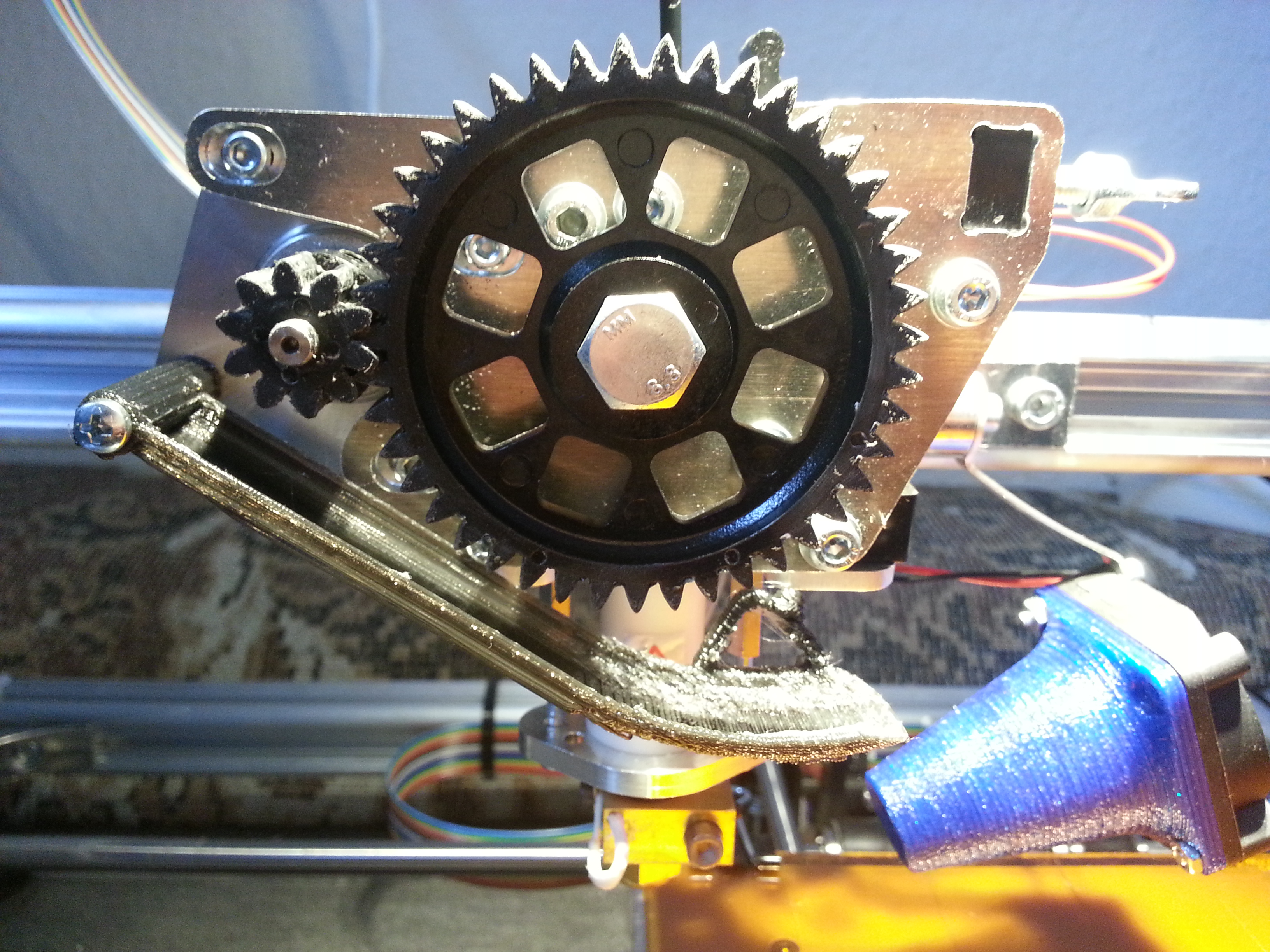
1. Add a dirt catcher under the extruder gears to prevent the dirty particles composed of ABS debris and oil from dropping on the printing bed.

2. replace the X-Axis pulley with a printed one, since the original one was out of round, which impairs printing quality!
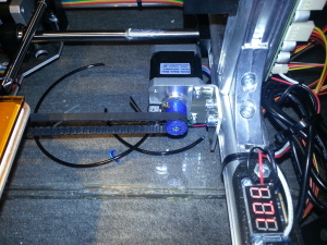
3. Add robust and precise homing system for the Z axis.
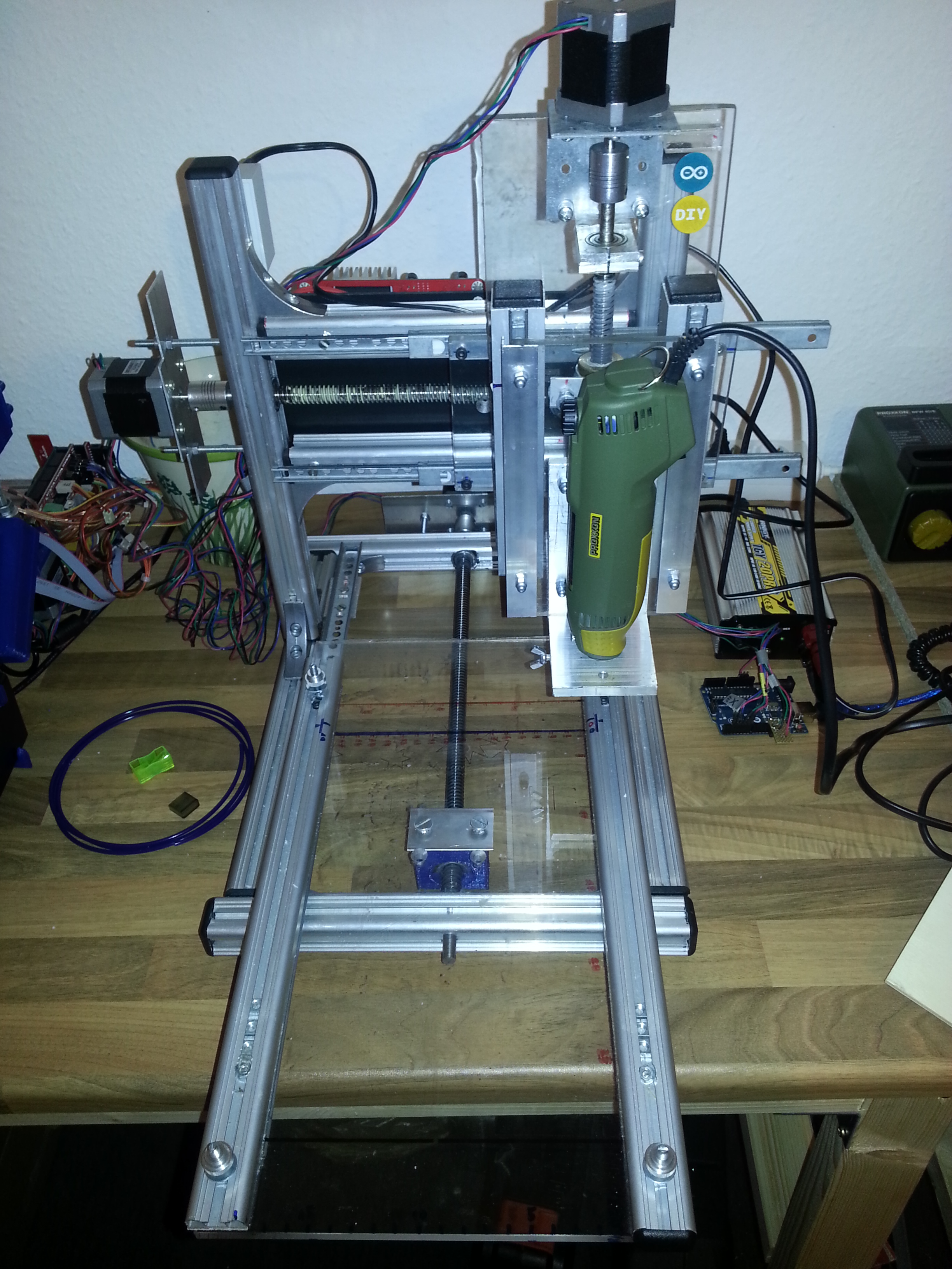
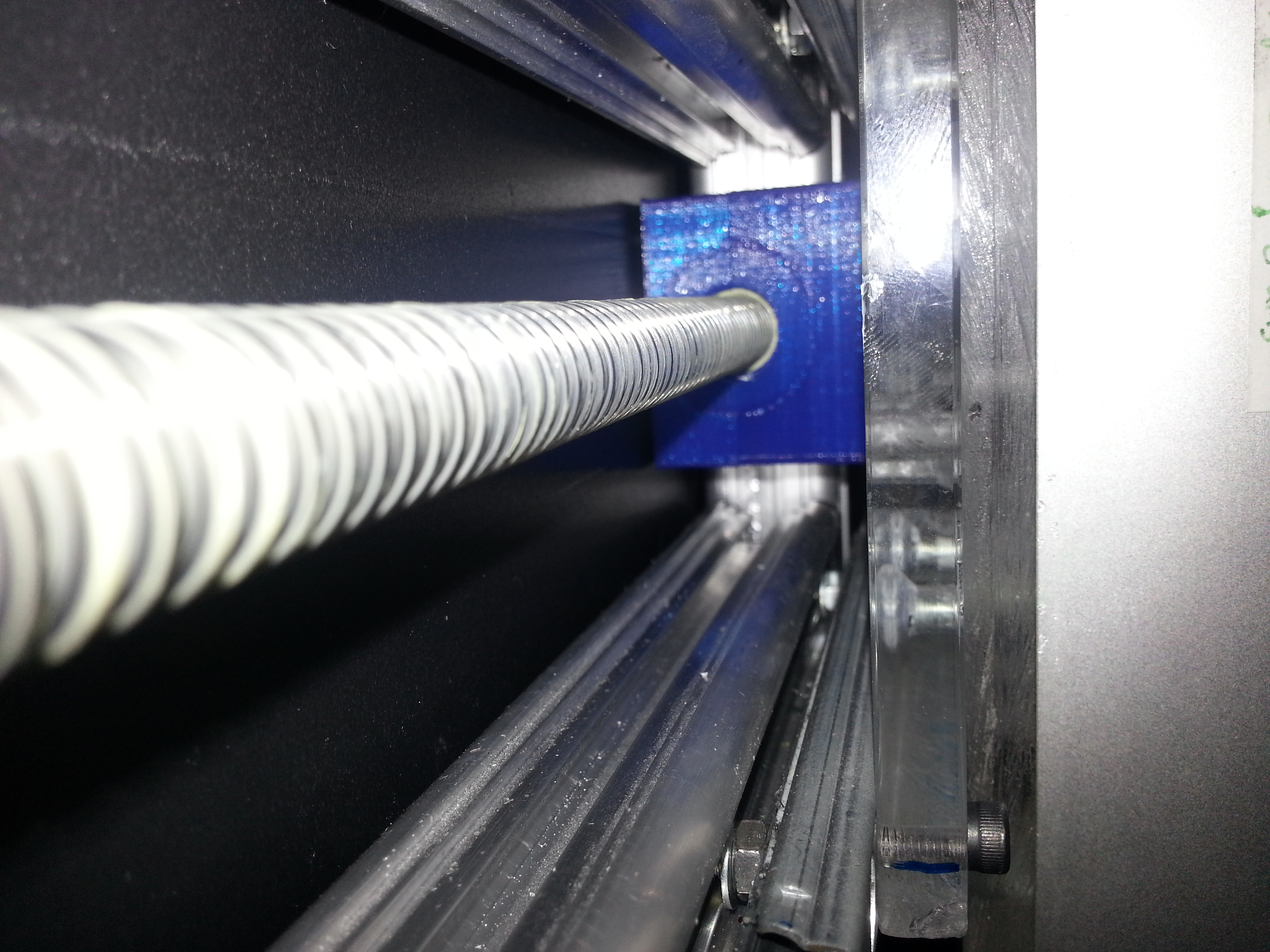
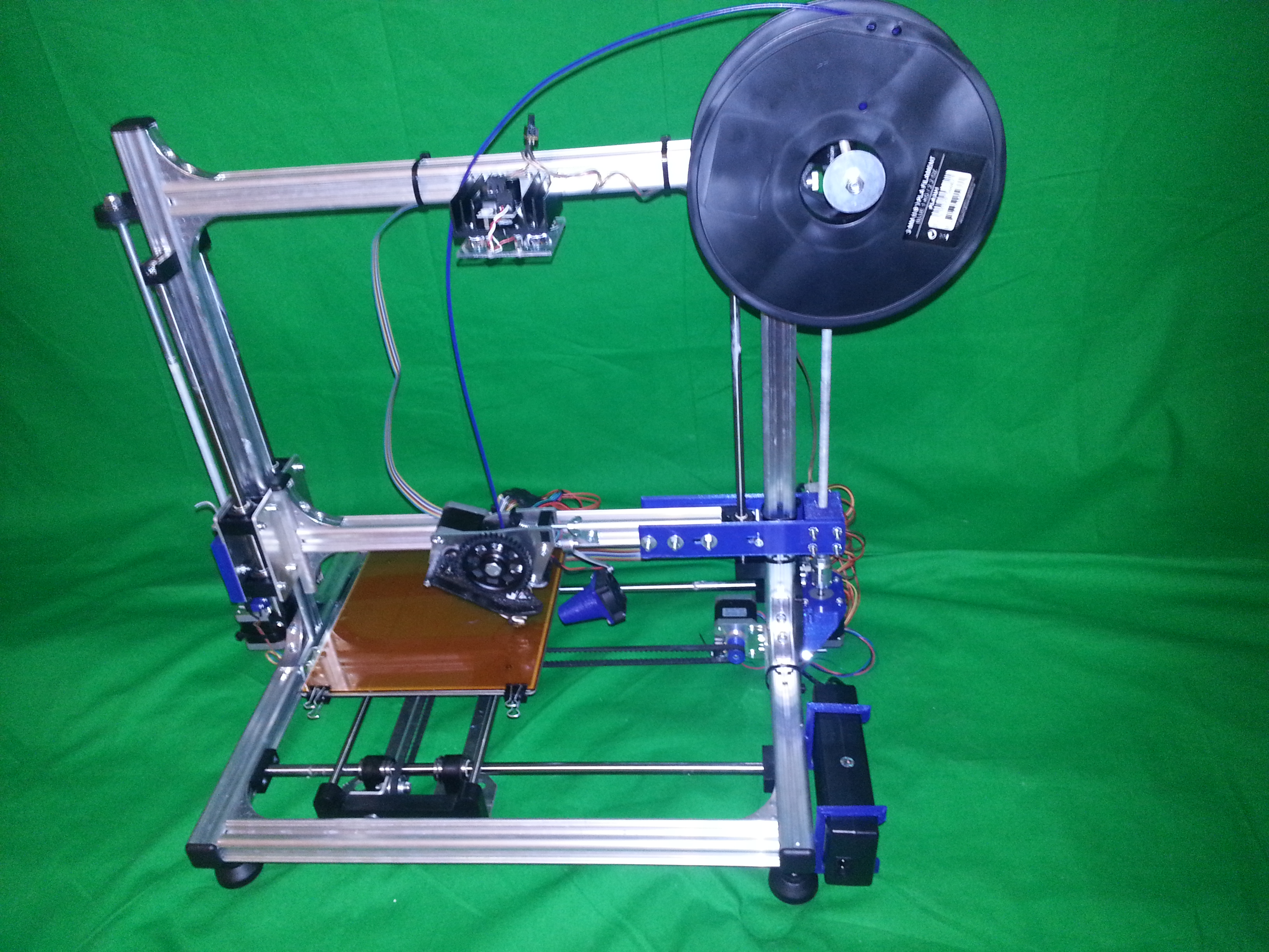
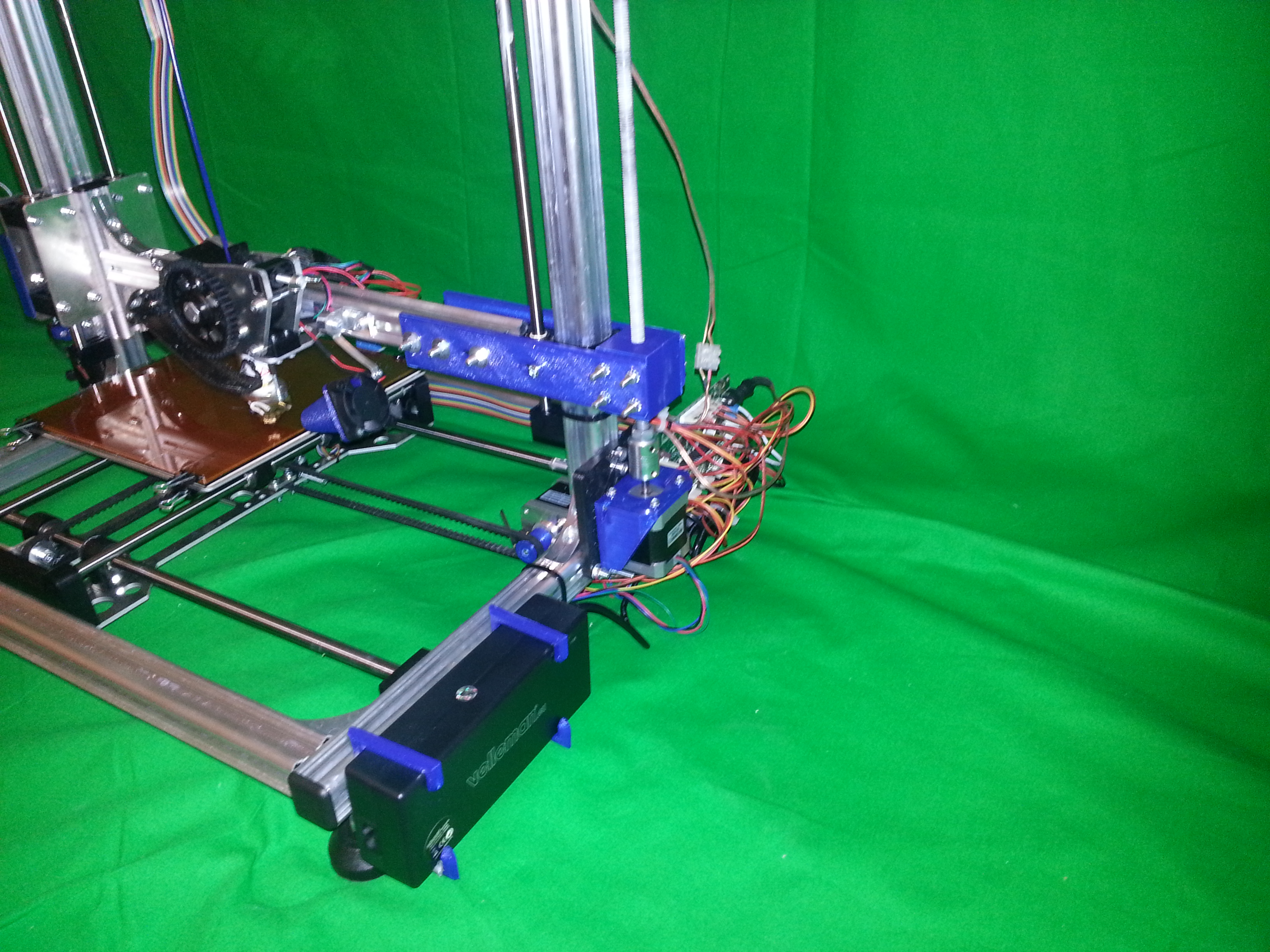
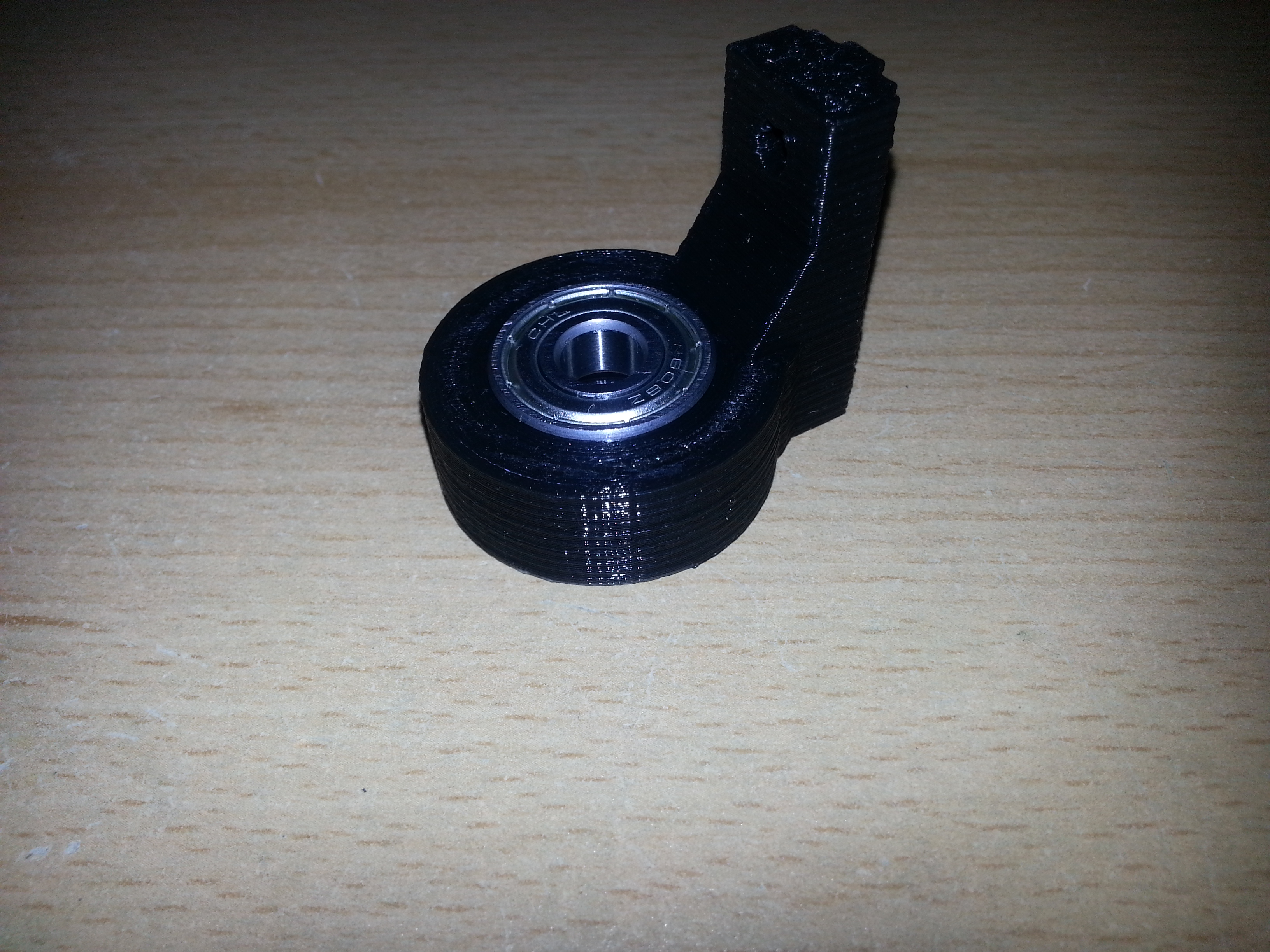
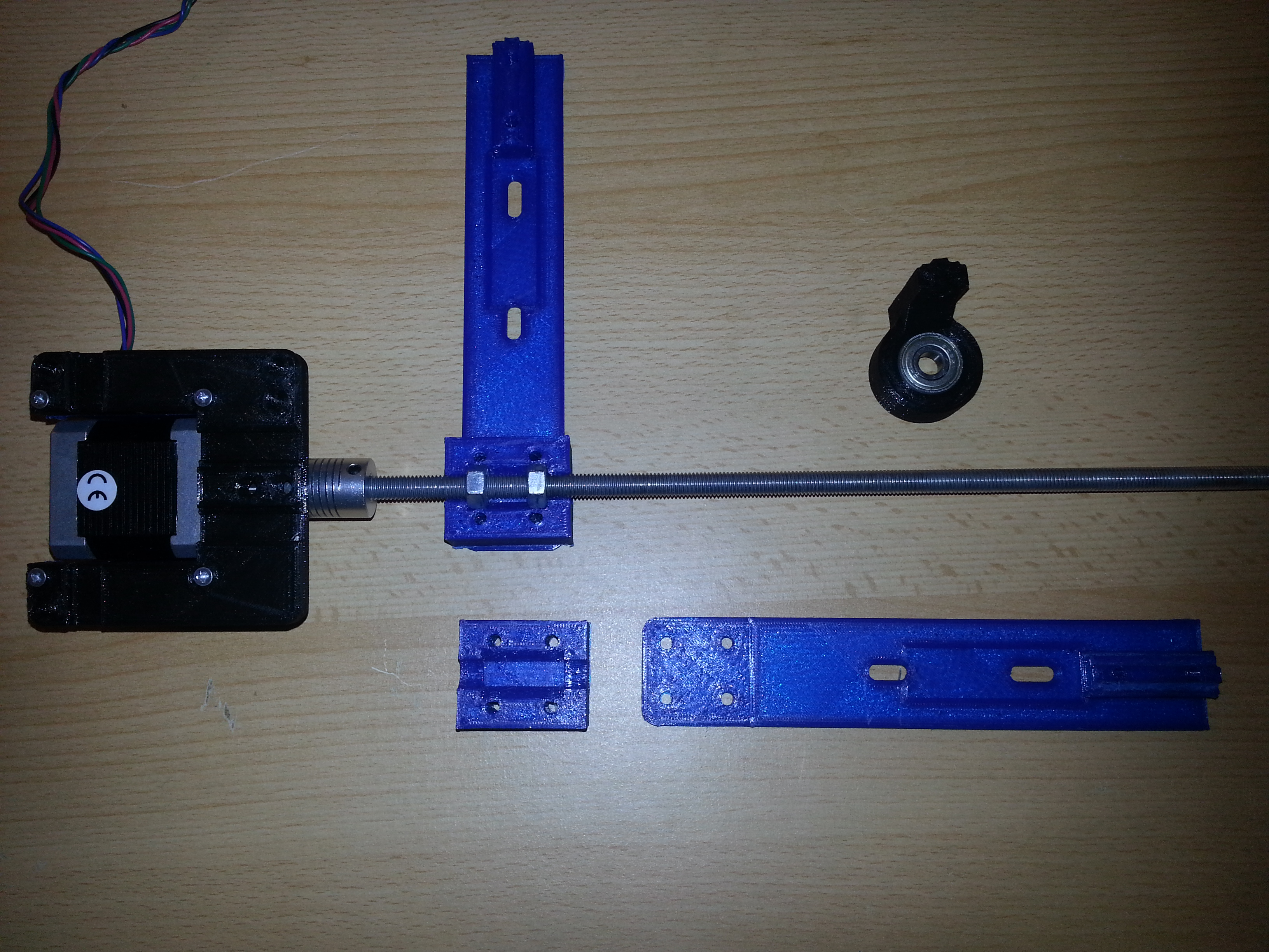
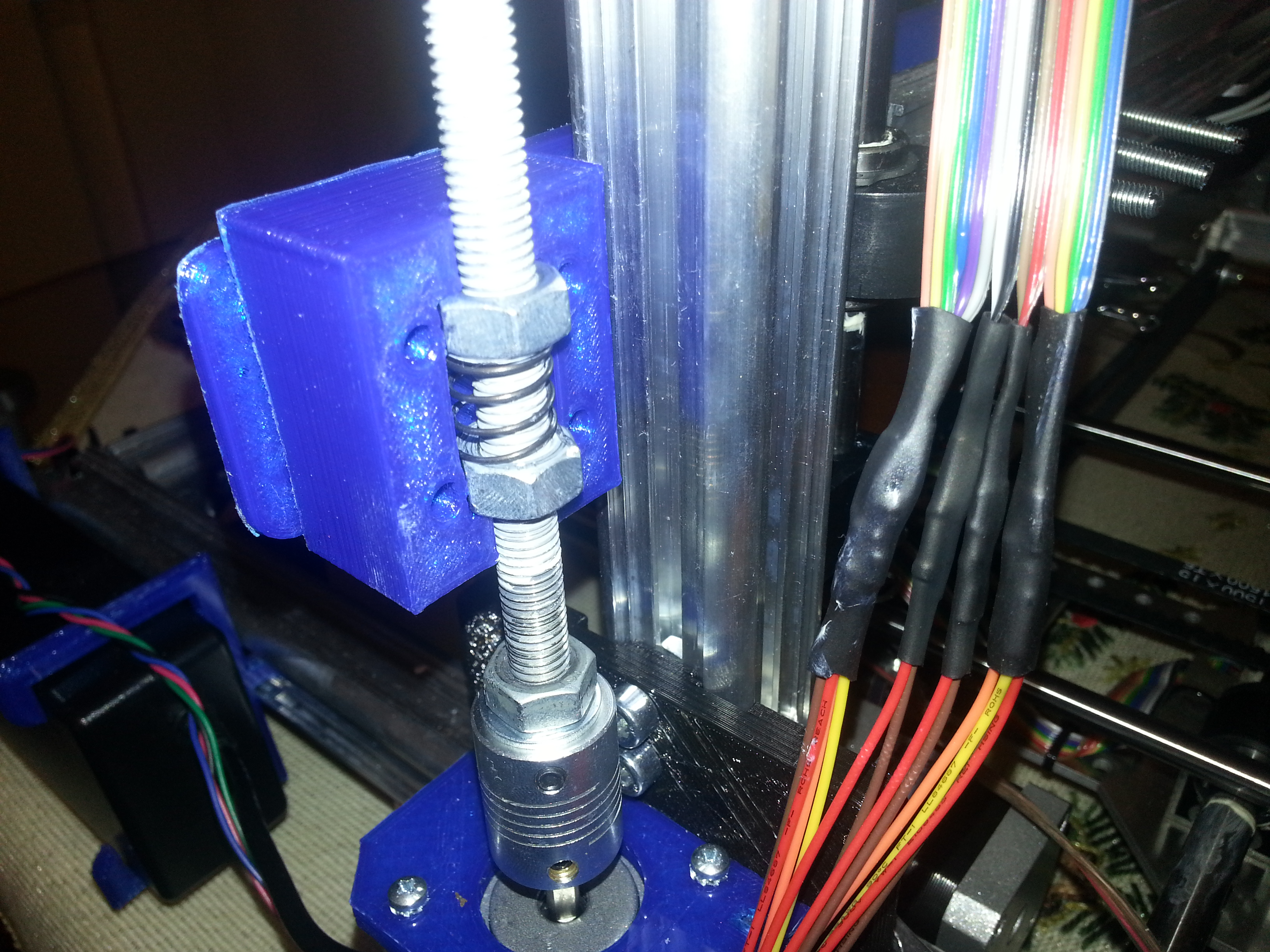
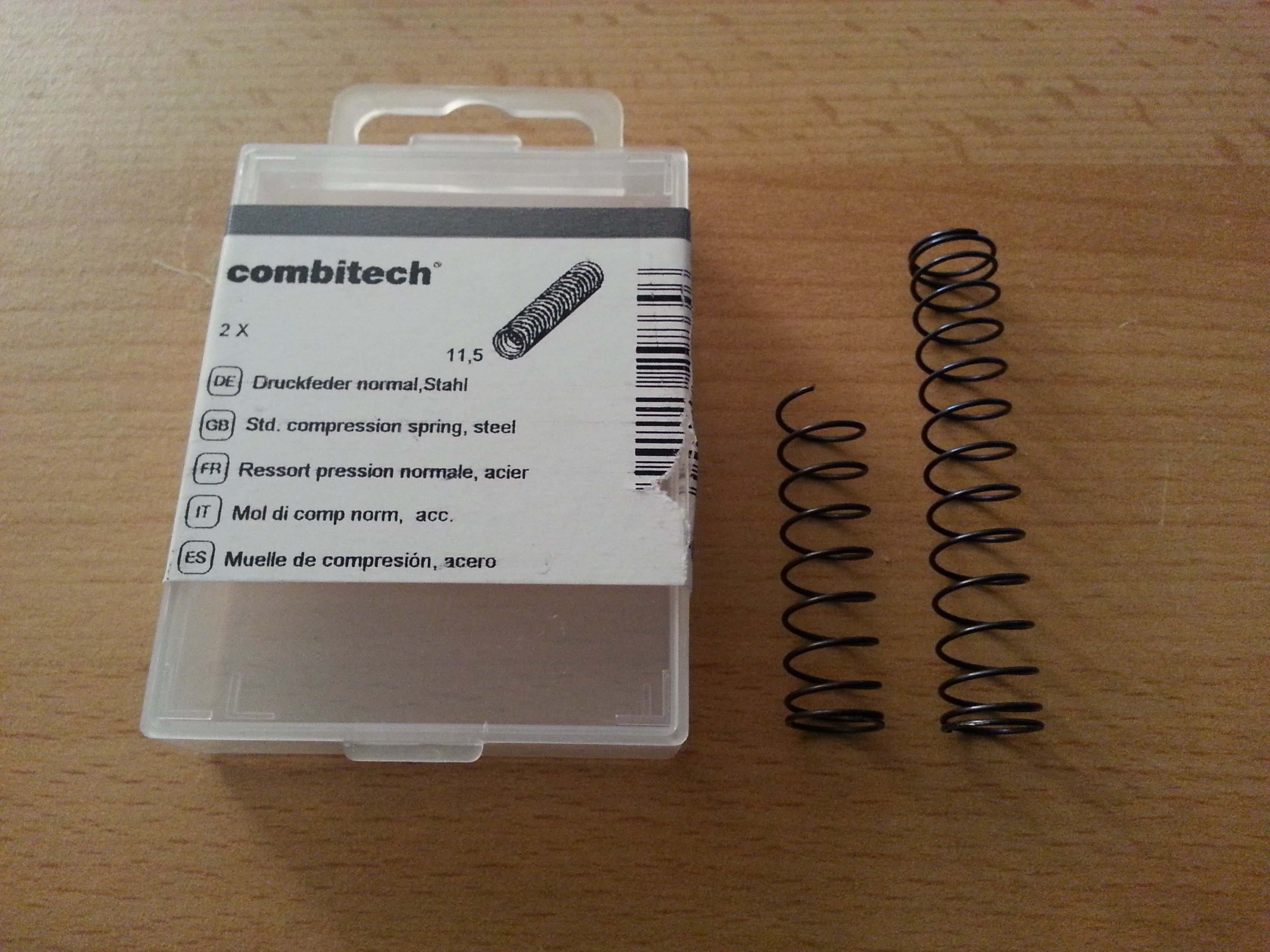
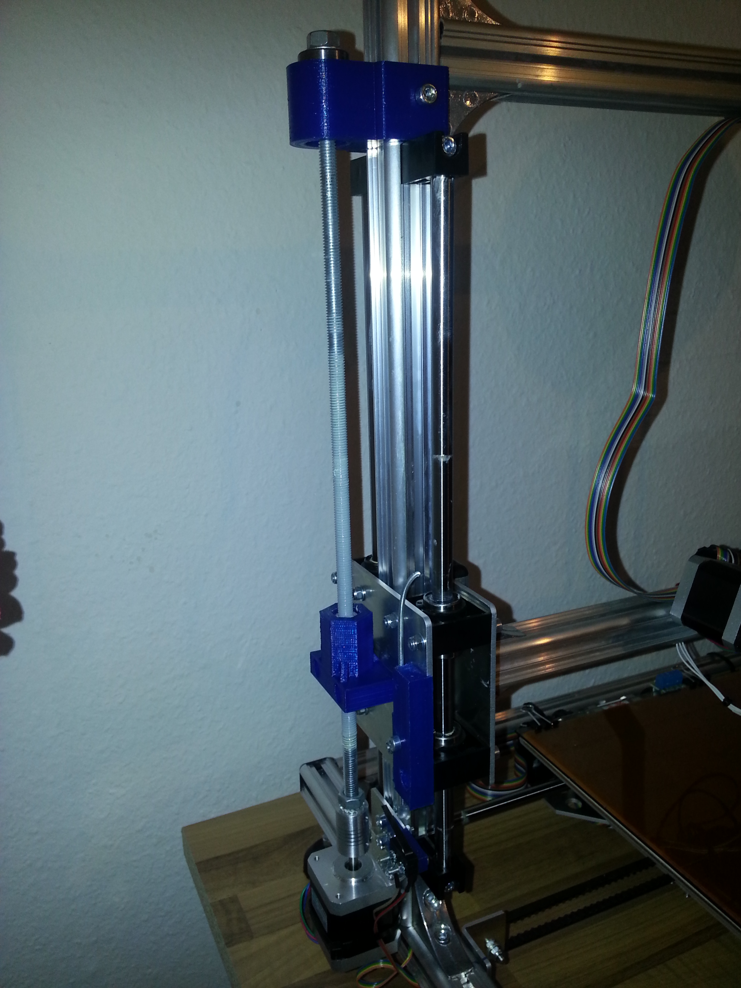
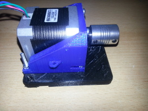
4. Extend the Z- Axis with a second spindle. I’m using another M8 stainless steel threaded rod with a flex shaft coupler and 2 regular hex nuts with anti-backlash spring. The motor mount and 608Z ball bearing holder are 3D-printed, as well as the arm extension. I’m not sure how this will affect print quality, but adding another spindle prevents the other one from wearing quickly. Also, like many other people, I have observed stronger vibration of the Z arm than on the frame itself. Eliminating it is not that hard and I had another NEMA 17 stepper and all the other parts lying around here anyway. My design can be found here.

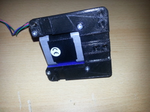


5: rebuild the left Z axis with more rigid parts:

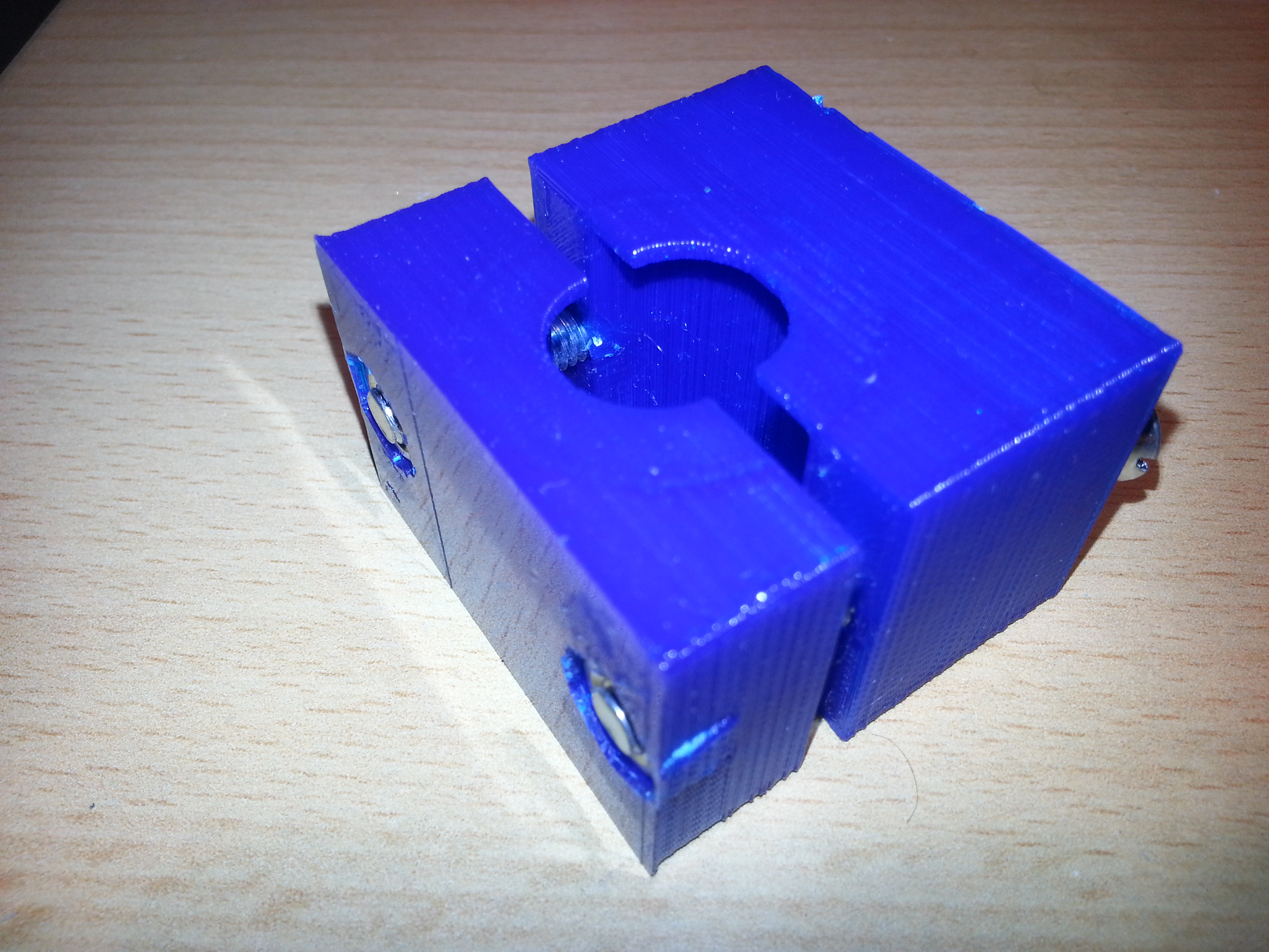
Z-axis Backlash eliminator
K8200 rod guide piecesholder STL can be found here
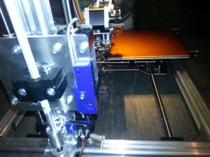
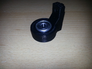
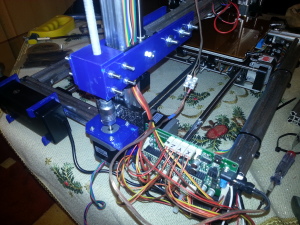
6. Mount a proper filament guide with a ball bearing on top of the LED light. This is supposed to have a very interesting function: since my printer lives in the attic, the filament tends to break, especially PLA is affected, during printing and when the filament spool is almost empty. The reasons are 1. low temperature and 2. tension in the filament as it unwinds from a smaller radius (the windings near to the core of the spool have a smaller radius). Before I begin printing something, I will turn on the nice 12W LED lamp which produces a lot of heat as a by-product. Since the filament makes its sharpest turn on its way into the extruder right where the heatsink of the LEDs is located, this is exactly the place where heat is needed. I hope that this will make filament shattering more unlikely in the future.
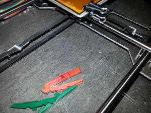
7. Add belt tensioners to the X and Y axis belts. these are simply springs from standard plastic clothespins that are bent to a proper shape, attached to the belts and secured with small zip ties. Watch out that the belts do not touch each other.
8. Add a filament spool holder with ball bearings. Maybe this will take off strain from the filament as well and prevent it from breaking due to the spool spinning unevenly.
here’s the thing
To do in the near future:
9. Update the firmware
10. Add an SD card holder, rotary encoder and a 20×4 LCD
11. make an enclocure for the elctronics
12. attach little heatsinks to the stepper driver chips
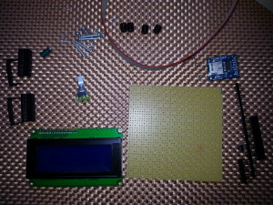
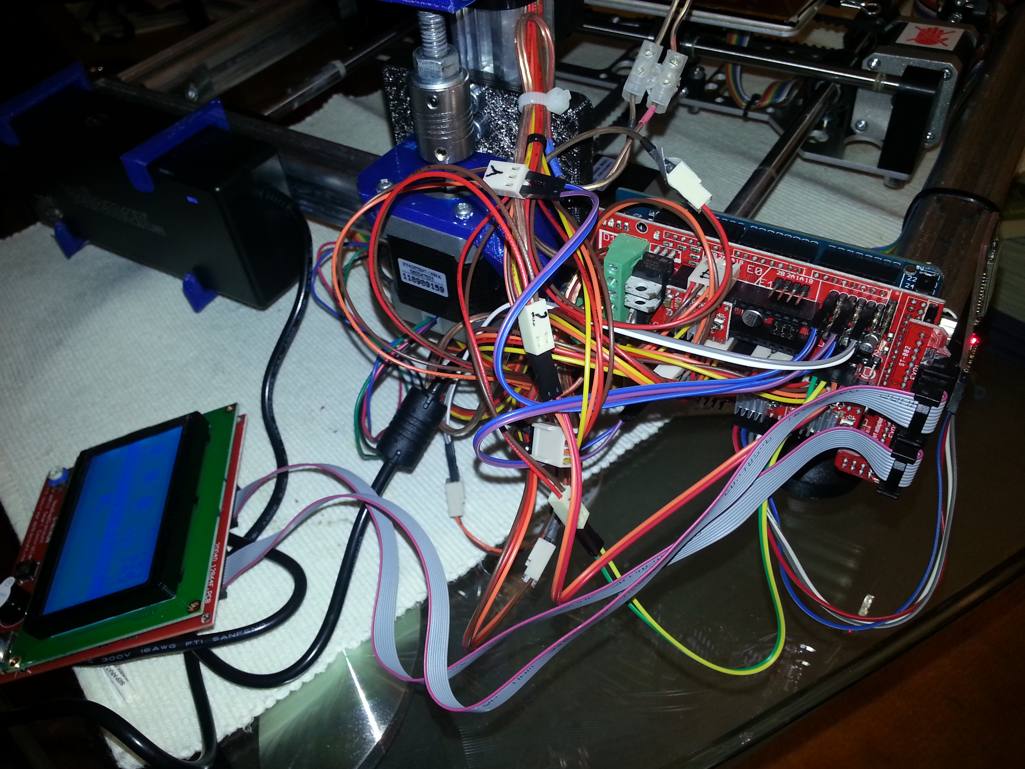
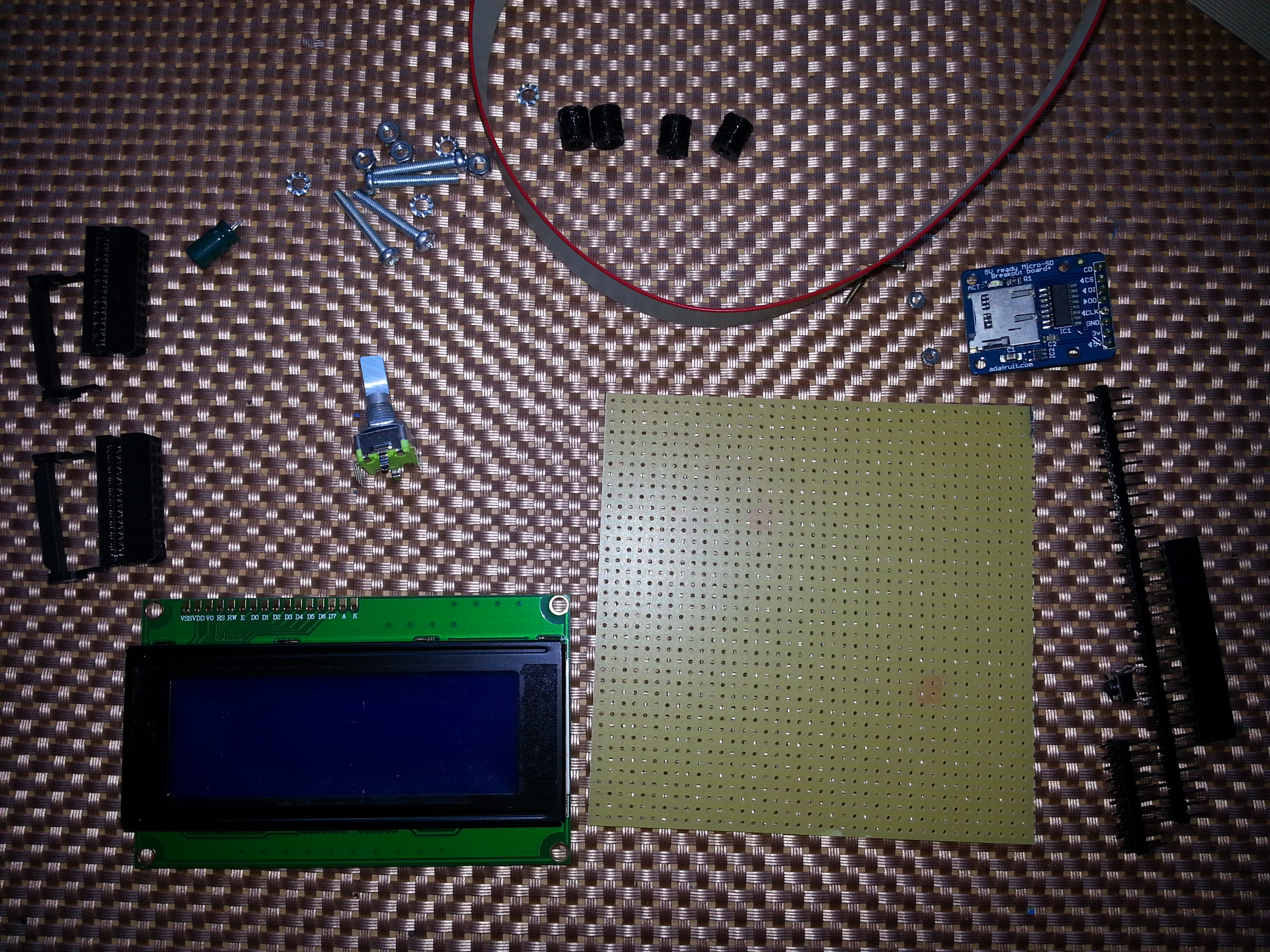
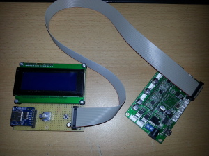
After realizing that a 20×4 character lcd, a (micro) SD card adapter with level shifter, a rotary encoder, 2×10 male & female pin headers and a ribbon cable is all that’s needed for transforming the printer into an autonomous device, I could finally start hacking again, because I had most parts lying around here anyway. What seemed to be a simple task, quickly turned out to become a little life lesson.
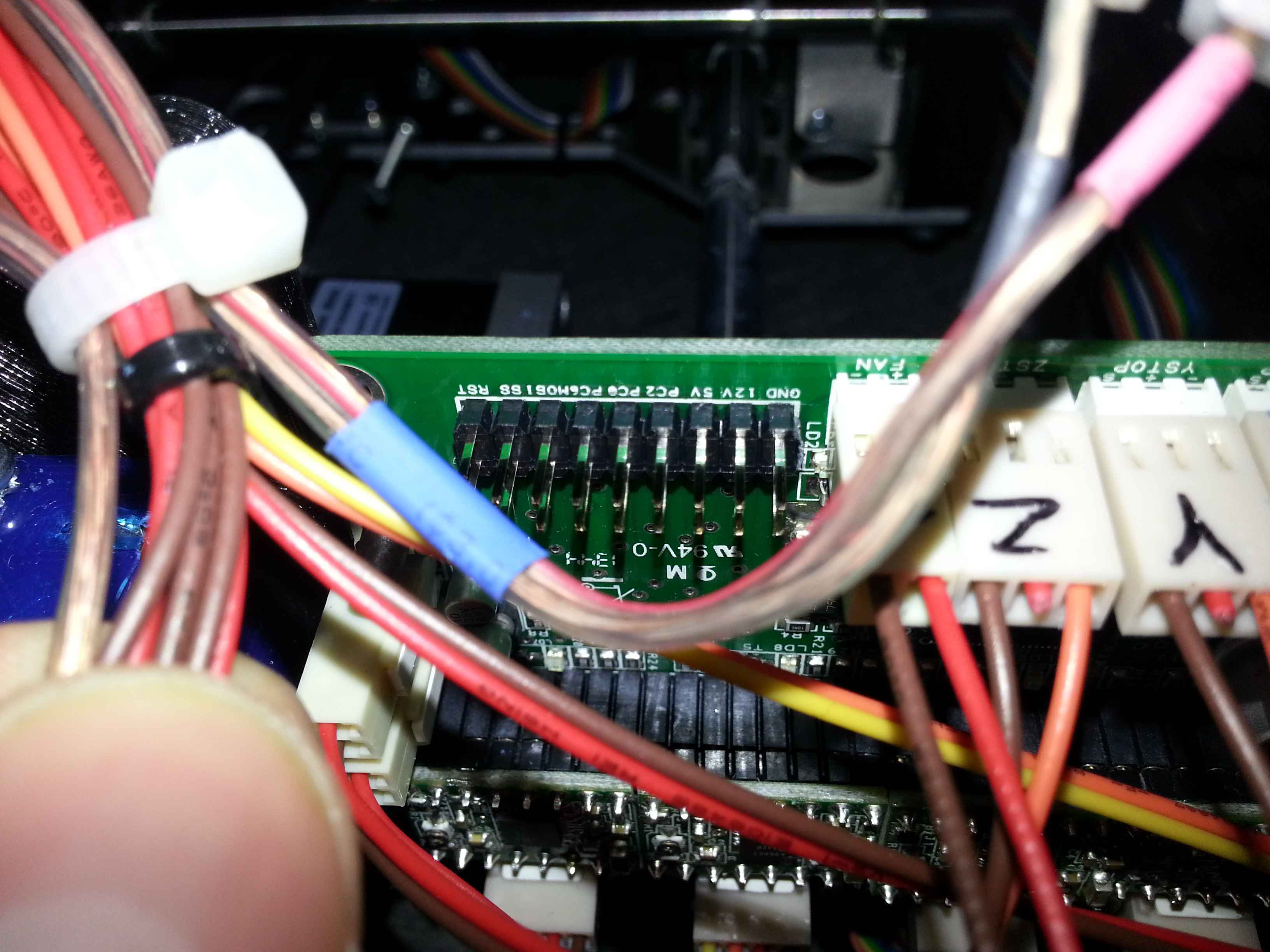
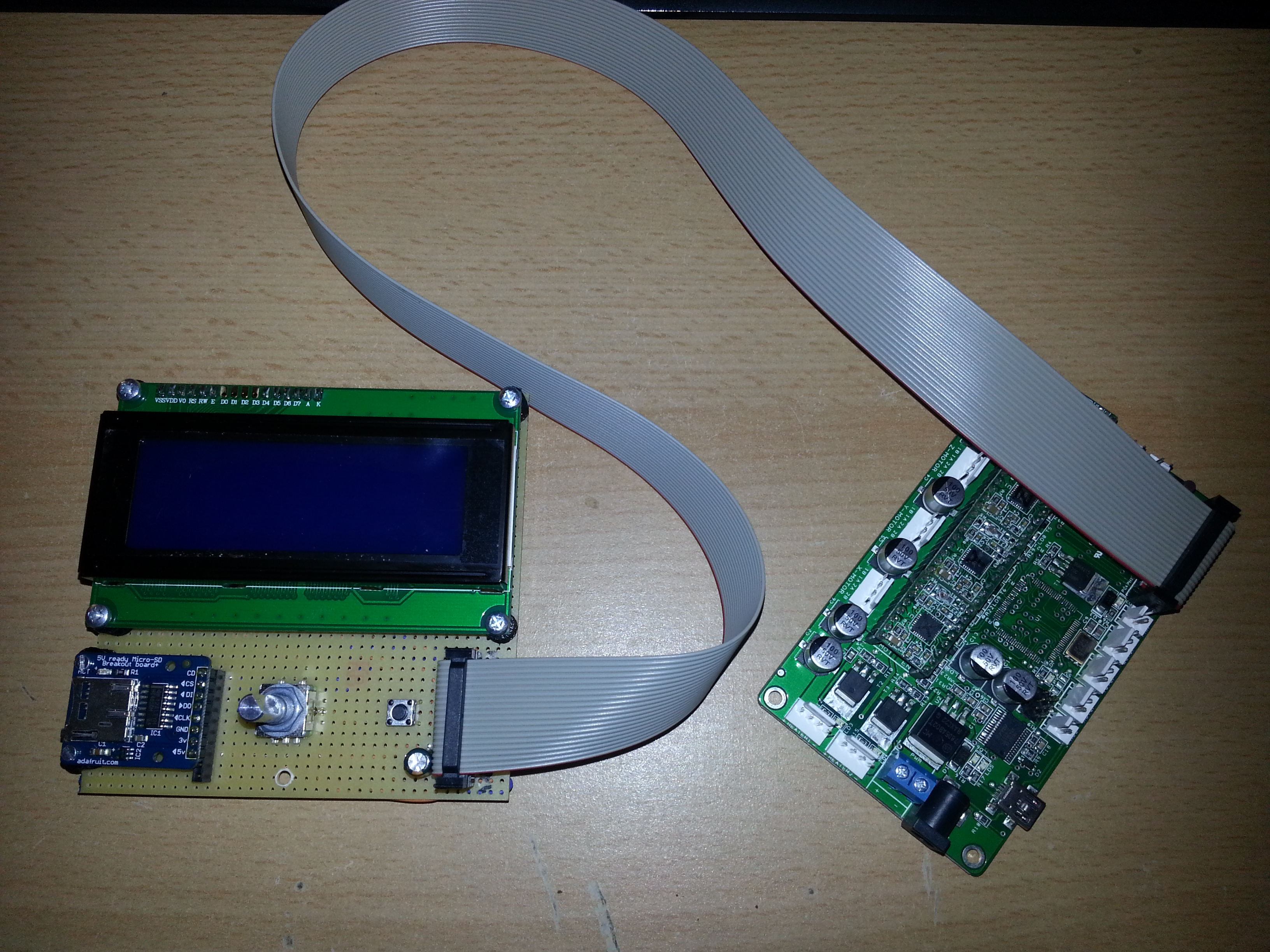
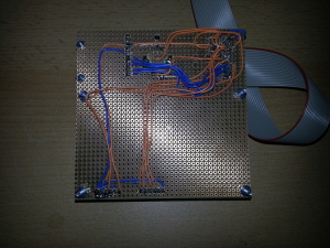
Since the K8200 Velleman kit is derived from an open source, RepRap-inspired project named 3DRAG by www.open-electronics.org, all schematics are freely accessible and its hardware as well as software are quite universal. Here’s the page with the schematics for the “autonomous board” that connects to the 2×9 pin header on the k8200/3DRAG control board. The schematics are quite simple, albeit not quite readable. Nontheless I soldered some pins onto the main board and started soldering up the LCD/SD/encoder board on a perfboard, which can sometimes take some hours if you wat a clean assembly.
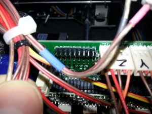
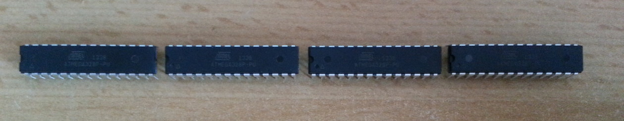
The excitement of getting the system to work as quickly as possible and improving the project forced me to overcome tiredness and hypoglycemia and in the end led to me swapping some dangerous wires, to be exact the motor supply voltage pin with some other port pin of the Atmega2560 microcontroller. Well, you can imagine what happened as the chip got 15 Volts on on of its GPIO pins! It died immediately. Before it died, I managed to do a firmware update though, which worked without any problems. Just short the “JPROG” pins together with a jumper and treat the thing like a regular Arduino Mega (with power supply connected, else it won’t upload). So this is what I ended up with:
I’m hoping that the FTDI chip and the stepper motor drivers have survived this terrible accident. The FTDI chip is at least recognized by the PC as a serial port device, I haven’t tested the stepper drivers yet. As for now I’ve removed the broken microcontroller chip and will try to replace it to see if the main board can be resuscitated. Having to de-solder re-solder a TQFP100 package is god’s punishment for being impatient and not taking a break during my build.
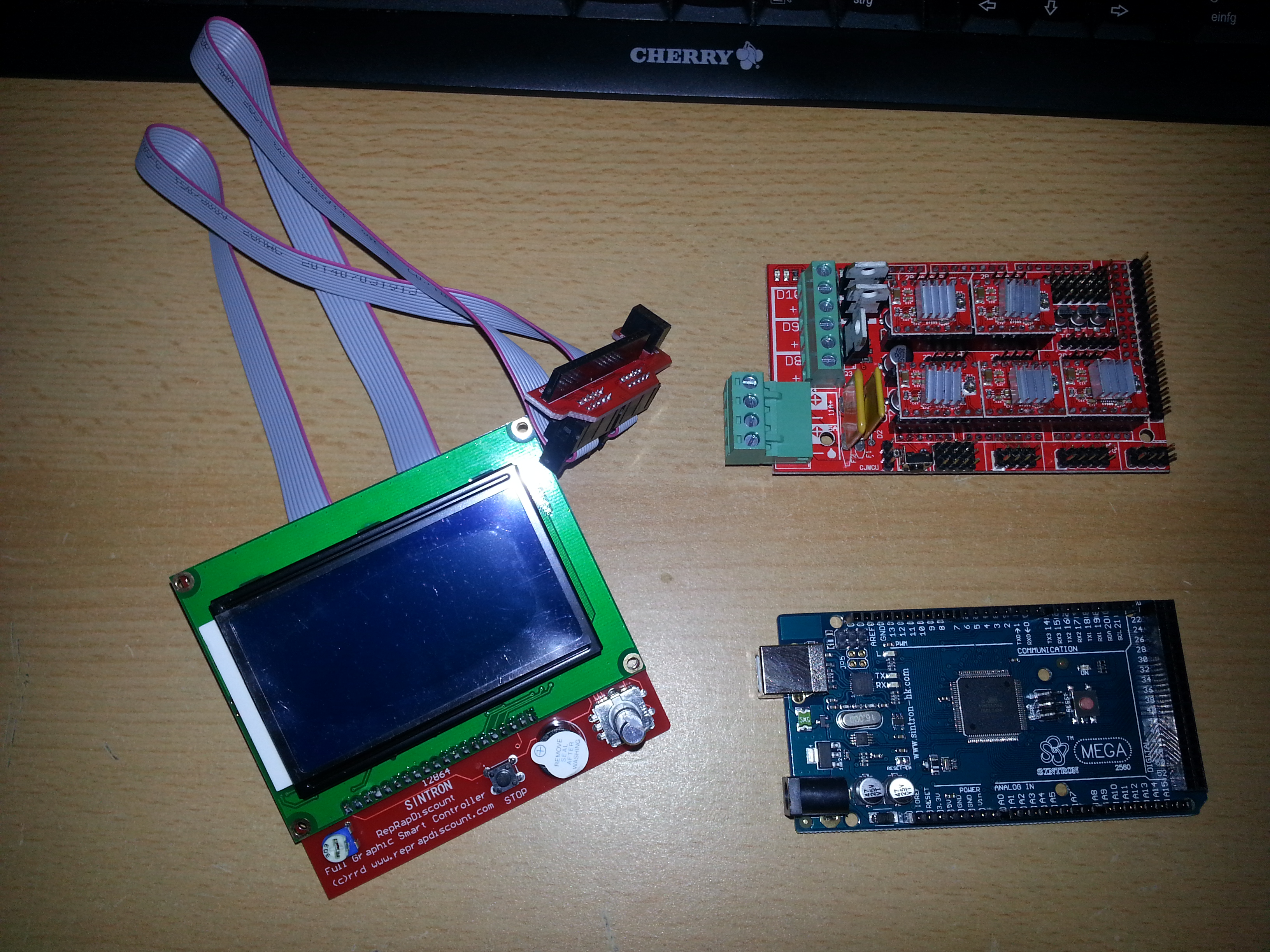
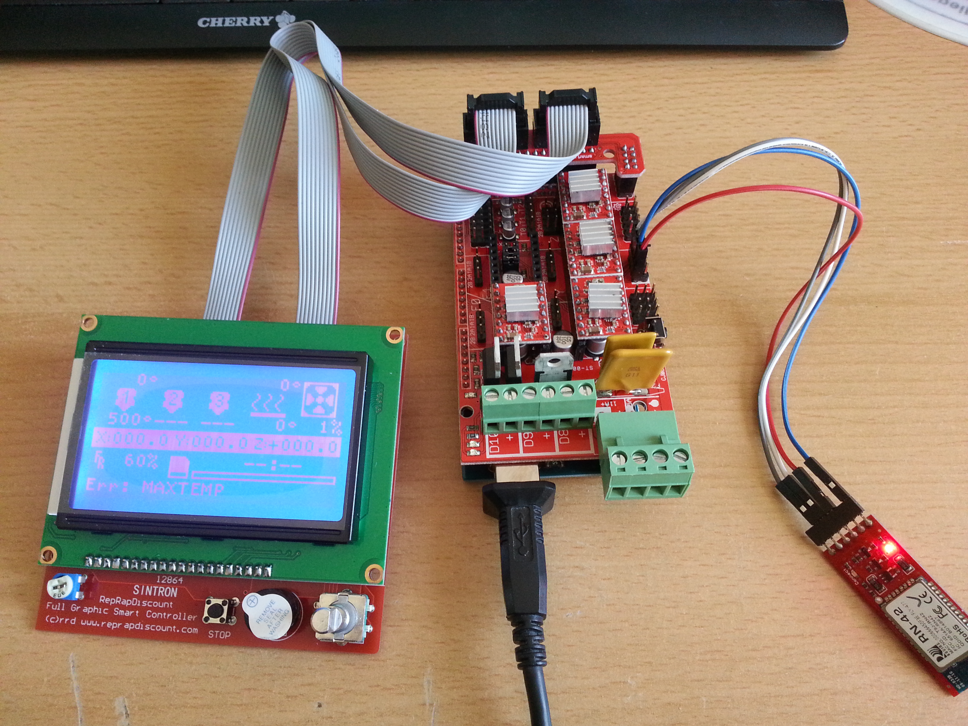
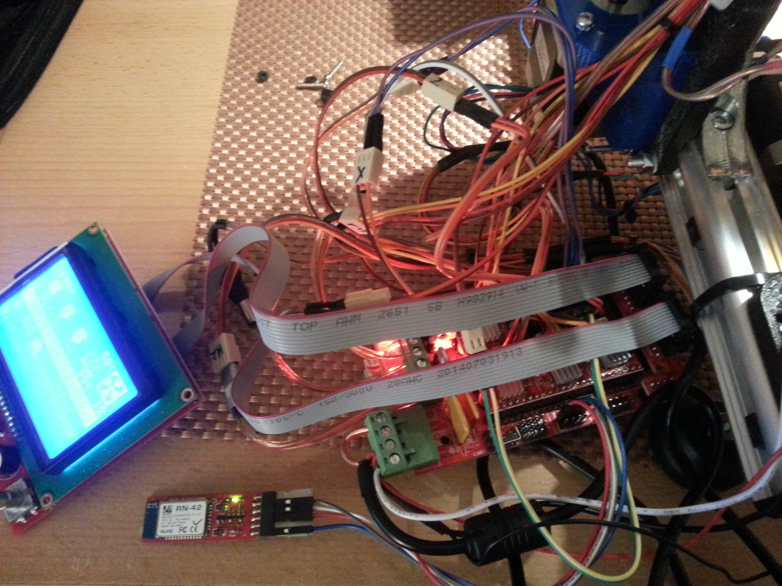
If replacing the microcontroller, flashing the Arduino Mega bootloader and Marlin v2 firmware doesn’t bring the main board back to life, I will probably have to install a RAMPS 1.4 electronics. This is basically the same electronics as the Original K8200/3DRAG mainboard, but a little more versatile, albeit a little less compact. They are available on eb** in various combinations. You have the possibility to connect a 128×64 graphics lcd and even a bluetooth module to the RAMPS 1.4 board, so this little crisis can even bring some new options as the ancient chinese saying states 🙂
Right now, I’ve corrected the bug in the wiring of the LCD/SD/encoder board and keep waiting for replacement parts.
Update: ok, so replacing the microcontroller didn’t resuscitate the board. I suspect that the stepper drivers and something else got fried as well. Actually not that surprising, as far as I have reconstructed the scenario correctly, 15VDC with reversed polarity might have hit the logic supply rails. After soldering the Atmega2560 I was not even able to flash the bootloader. Despite using plenty of flux and producing neat-looking solder joints nothing seemed to work. The chip was supposed to have the wrong signature according to avrdude. I tried overriding that error and doing the upload anyway, but that didn’t yield any results at all. Not even the fuse and lock bits could be configured. After touching all pins with the soldering iron once again to make sure that there are no “cold” solder joints and removing all stepper drivers, a different error was displayed. “Device doesn’t answer…” After a while I gave up and ordered a complete RAMPS kit with a RepRapDiscount Full Graphic Smart Controller and a complete set of new stepper drivers. Maybe I’ll try tracing down the error, but not right now 🙂 I’ll open up a new blogpost on the RAMPS setup on the k8200.