I’ve been intrigued by the ADS1299 chip by TI for a long time and after I came across the OpenBCI project and felt that my SMT skills were good enough, I finally decided to give the DIY approach a trial. The documentation is very good and almost complete and everything is open source, so get ready for an exciting blog post.
First off I downloaded Design Spark, which is the PCB editor the OpenBCI designs were made with. I used it to generate gerber files for getting the boards and solder paste stencils manufactured by OSH Park. By now they even have a function for importing Design Spark files.
Anyway, here are the Gerber files for the OpenBCI V3 8bit board. You should be able to place OSH orders using these:
OpenBCI 8bit OSH Park
For OSH Stencils:
OpenBCI 8bit OSH Stencils working
32bit Gerbers:
OpenBCI 32bit
32bit board stencil Gerbers:
OpenBCI 32bit Stencil
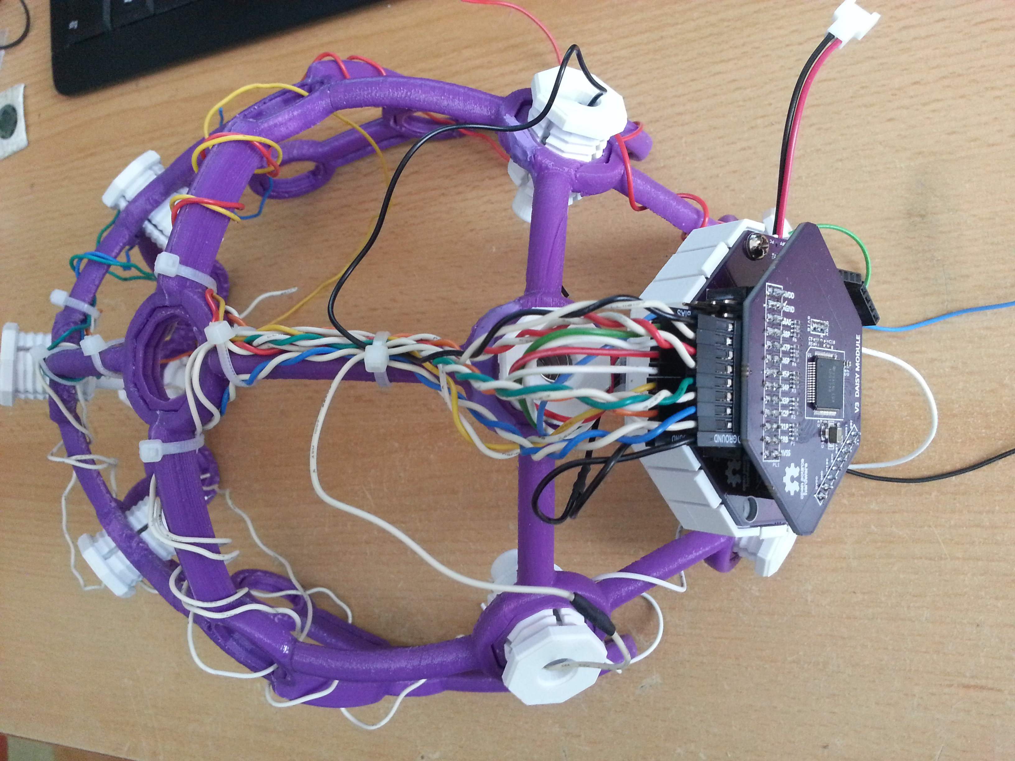
Daisy Board Gerbers (the 8bit board stencil partially fits the Daisy board, therefore I didn’t generate stencil Gerbers for that):
OpenBCI_Daisy
Note that there’s a bug on the Daisy PCB, which is described here.
luckily I knew about that issue and fixed it during the “pick and place” process prior to soldering.
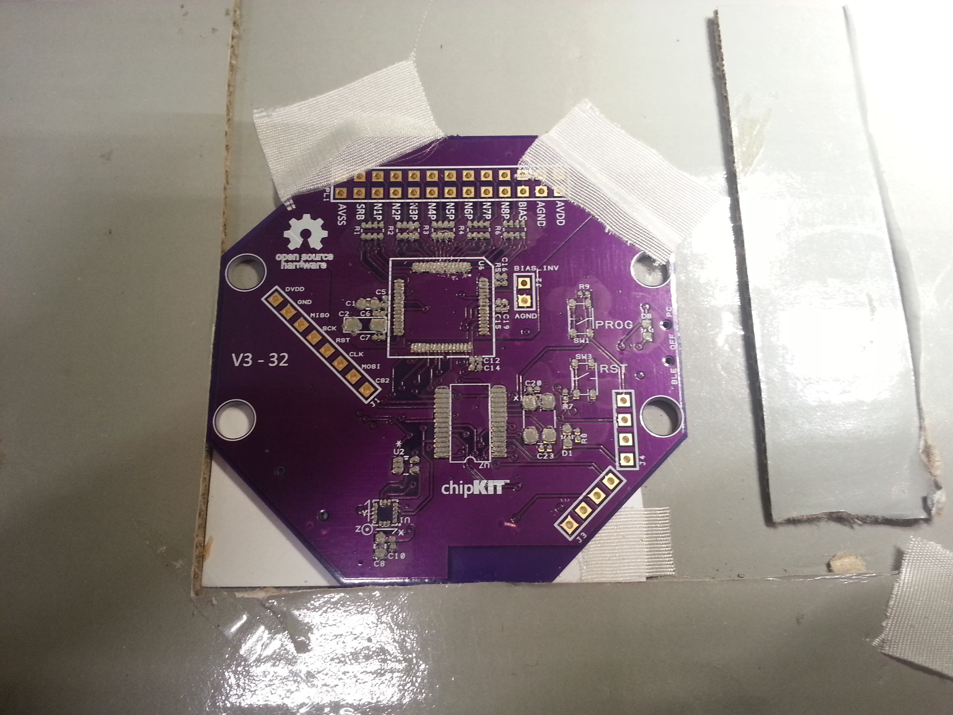
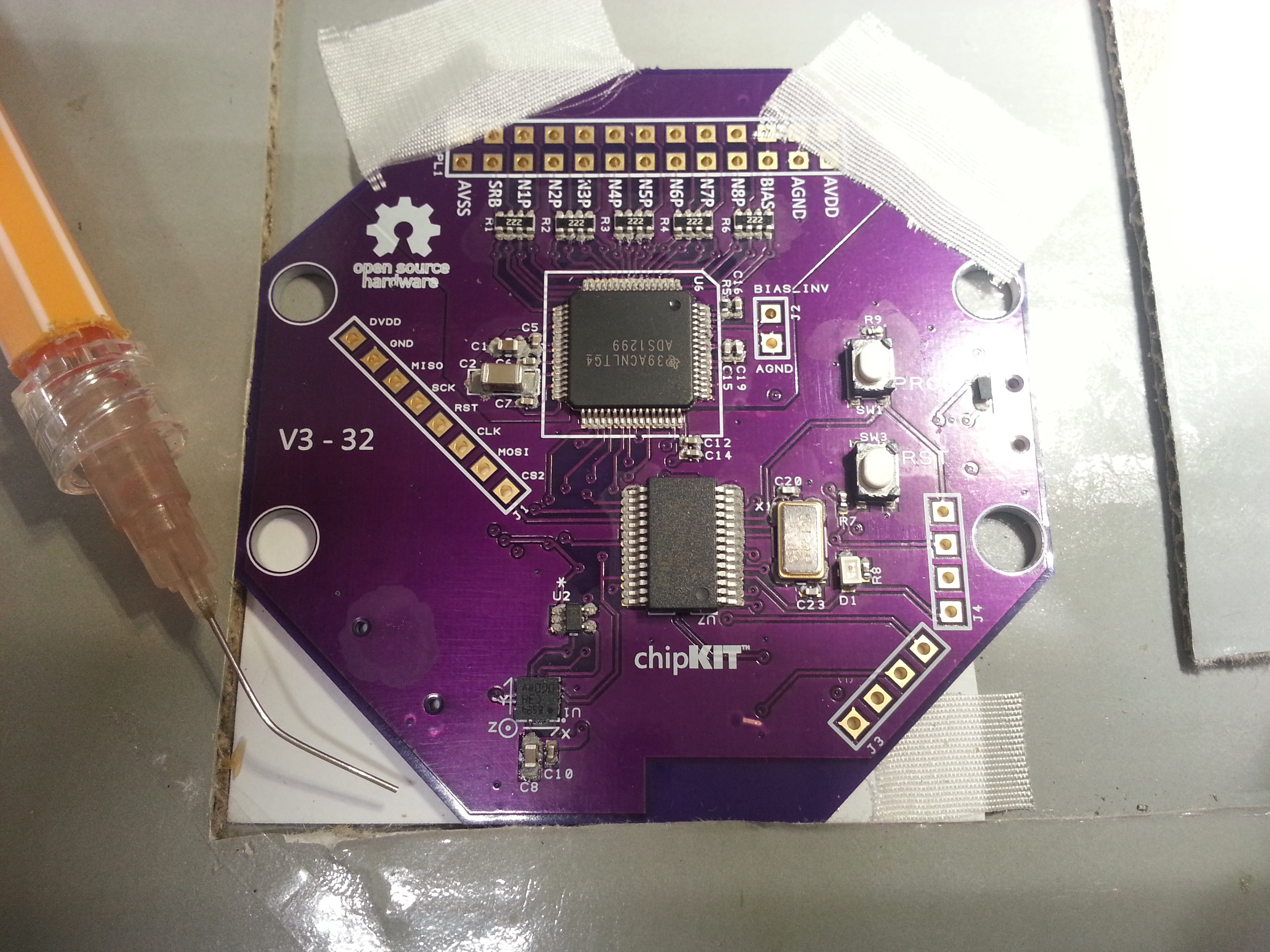
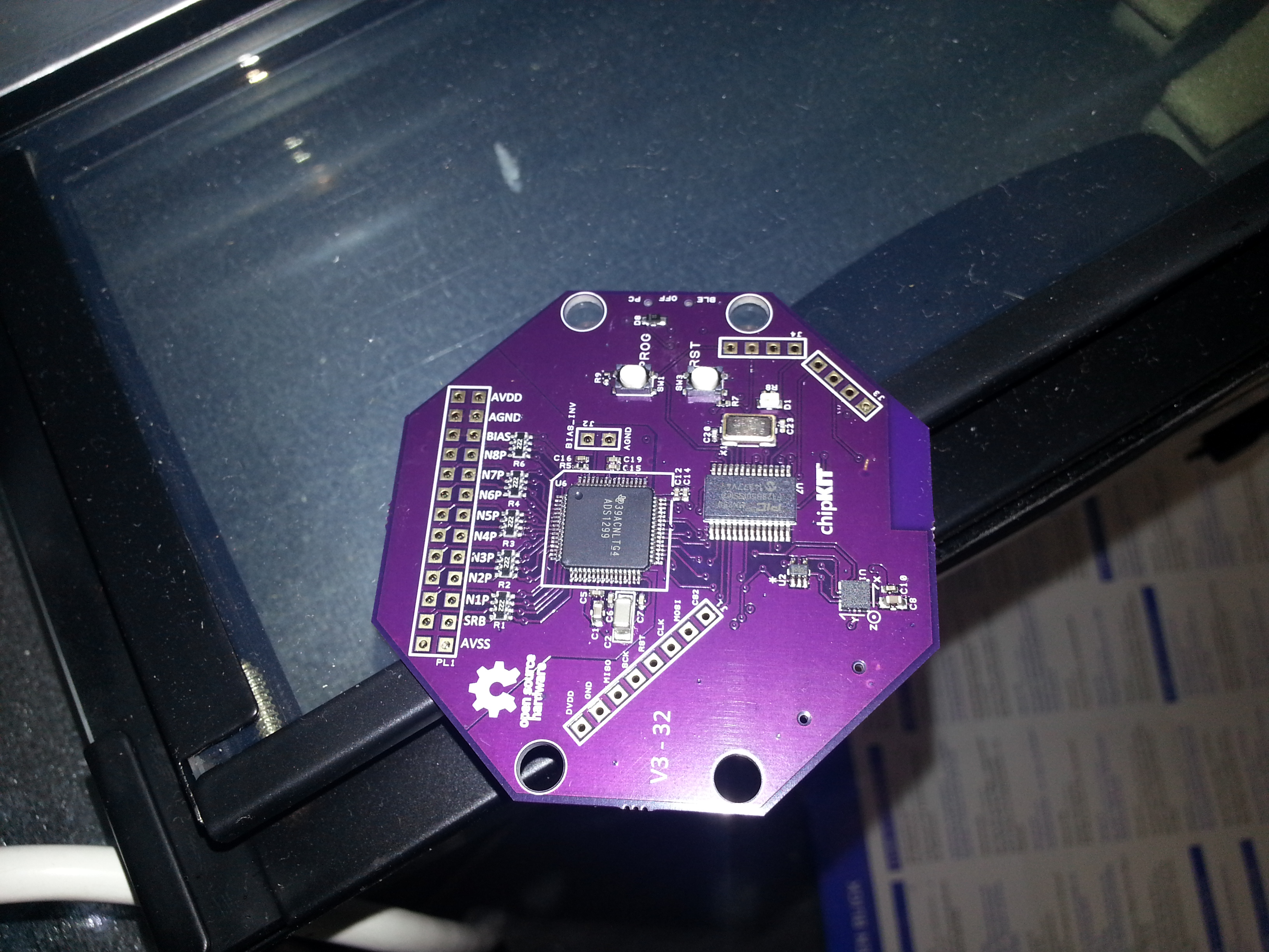
I would recommend building the 32bit version right away since it is more capable (writes to SD, can be upgraded to 16 channels, fewer power rails, runs from one lithium cell, no need for 5V+, better microcontroller and last but not least: easier to build since it has fewer parts!).
Most parts were sourced from Digikey and Mouser. The SD card holder I found somewhere on ebay.
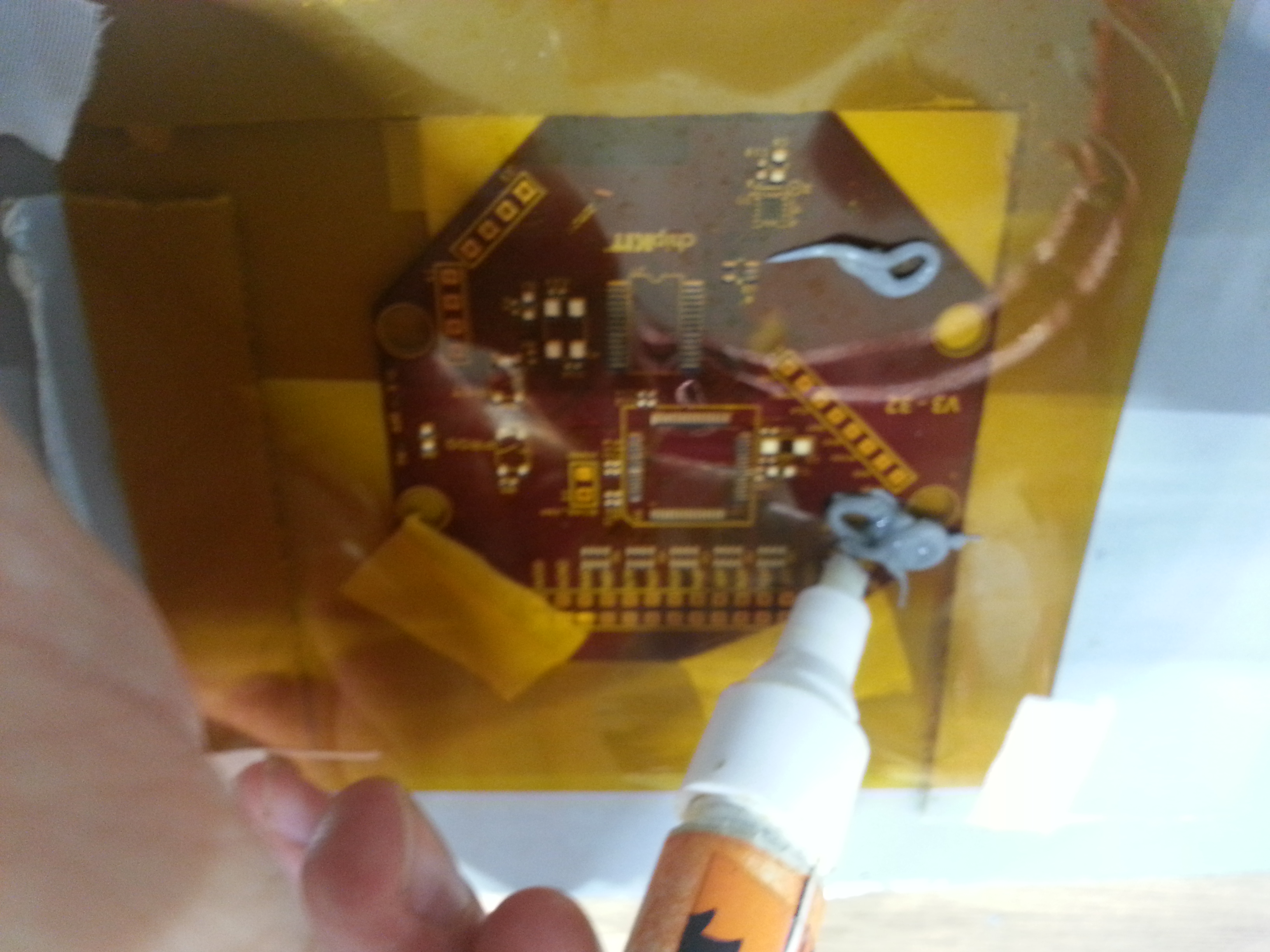
Also, I found picking and placing of tiny 0402 parts worked best with my DIY SMD vacuum tool and a thin needle. Especially where the components are densely packed (below the ADS1299) this method was very helpful. Before you begin, make sure to print out the OpenBCI_32bit_BOM and stick the component tapes with gluestick or sticky tape right next to the part indices. That way no parts get lost and you know exactly where each one belongs.
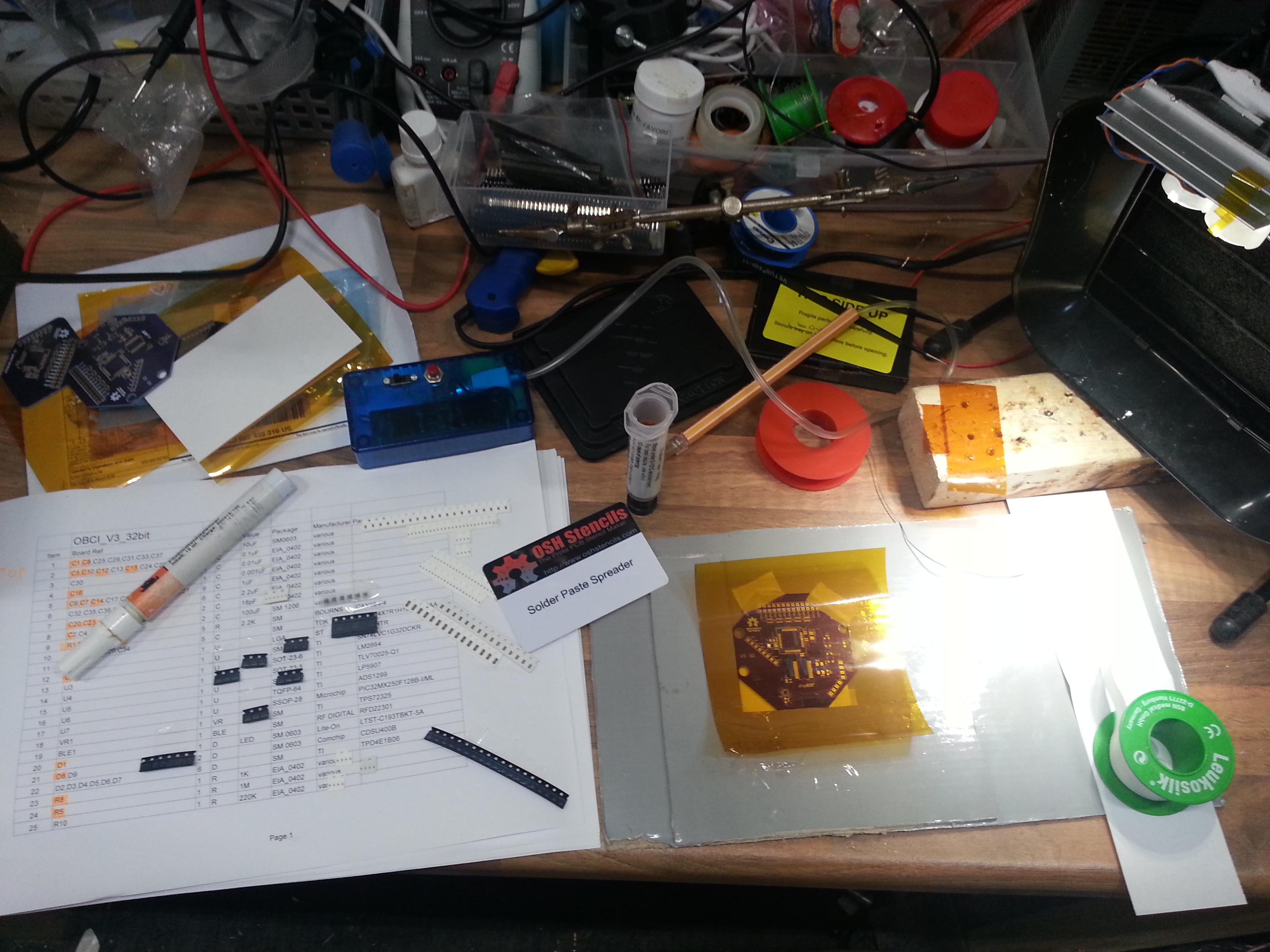

I had better results adding a drop a thin flux from a flux pen into the solder paste and mixing it. That way the solder paste is a bit smoother and reflows better. Remember: you can never use too much flux!
The top side goes into the DIY reflow oven
The bottom side is soldered with a hot air tool, being careful not to overheat the PCB.
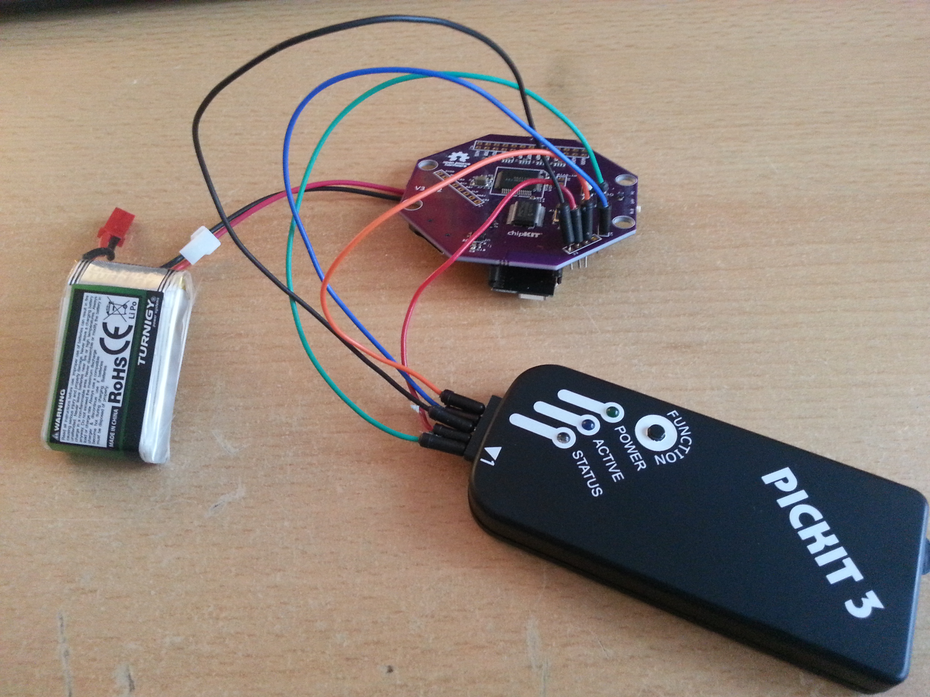
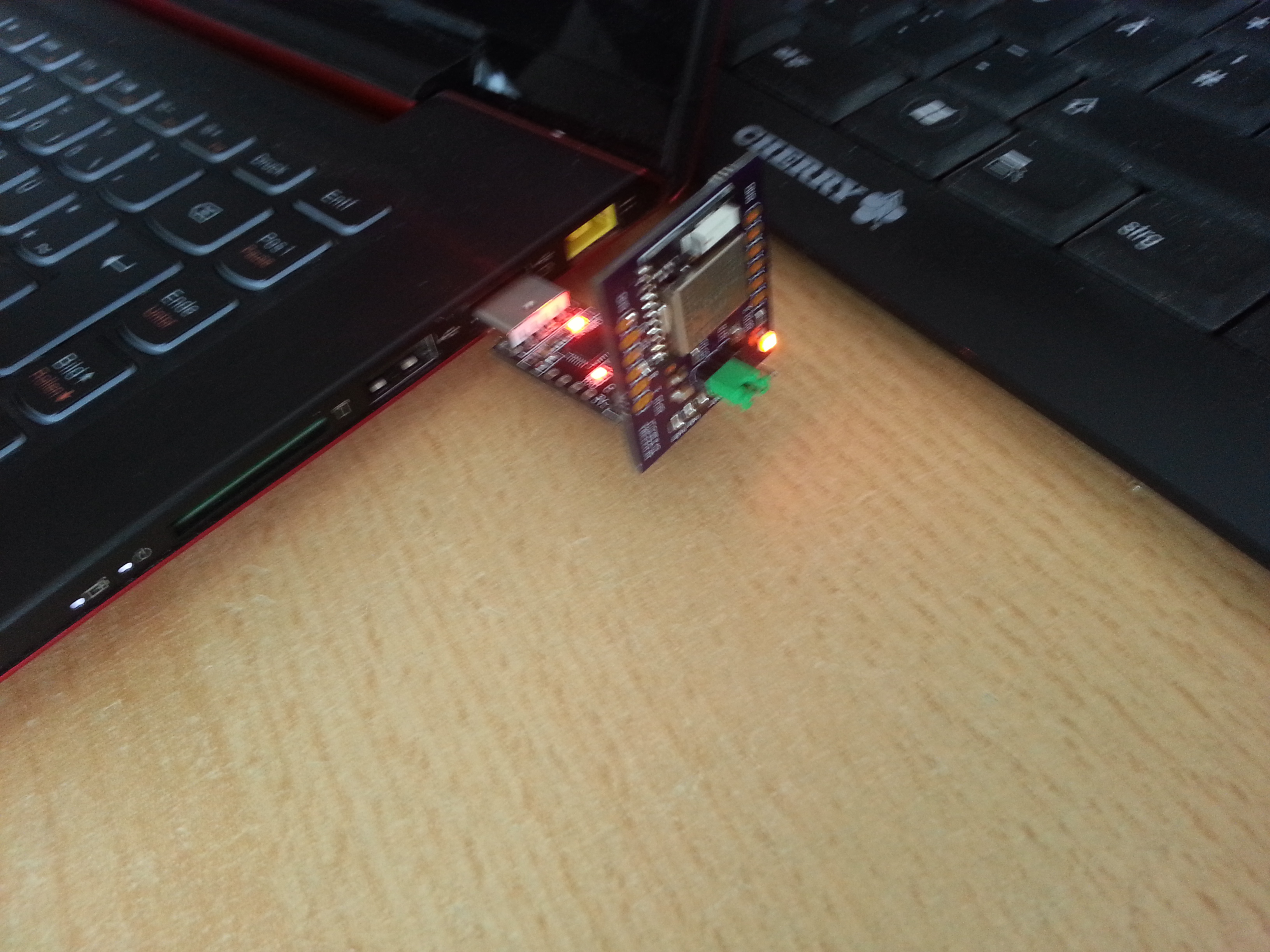
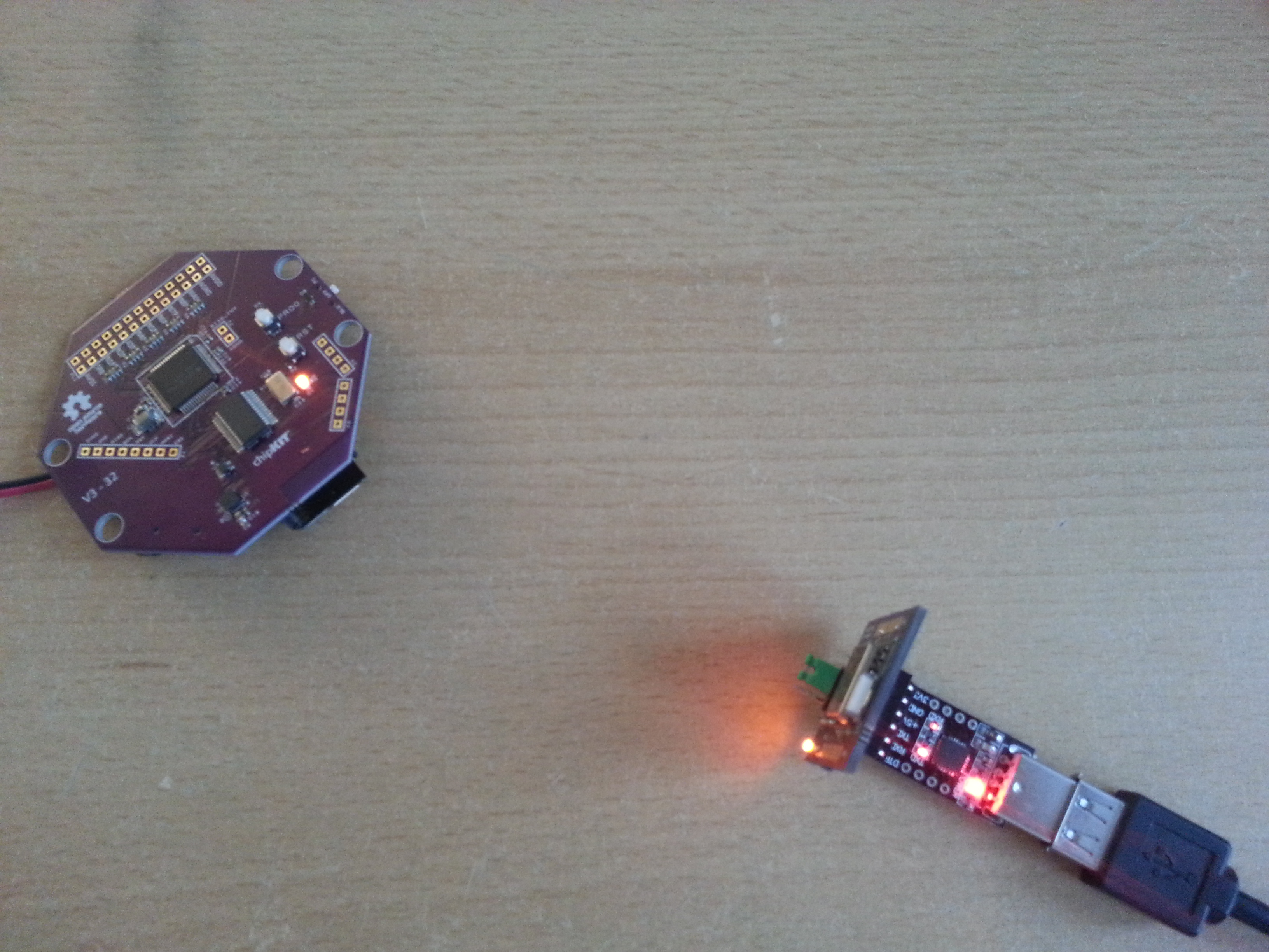
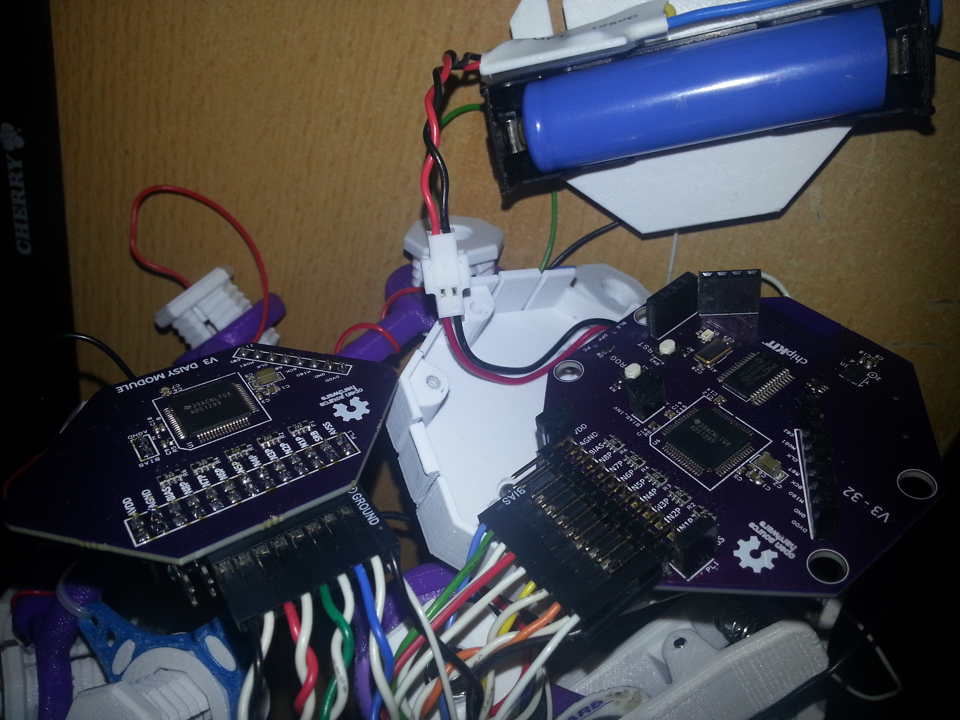
I’ve soldered 1.27mm header pins to the RFduino and female headers to the PCB because the wireless link is the bottleneck of the system. The headers allow to connect a different wireless module such as BT 2.1 or a USB-serial converter, which could be useful when planning to increase the sampling rate or using the system with Android devices.
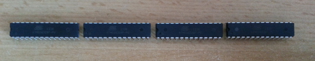
Using the PICKIT 3 programmer and MPLAB IPE (you can install ithe IPE without installing the IDE) to flash the Chipkit bootloader (can be found in the OpenBCI Github repository).
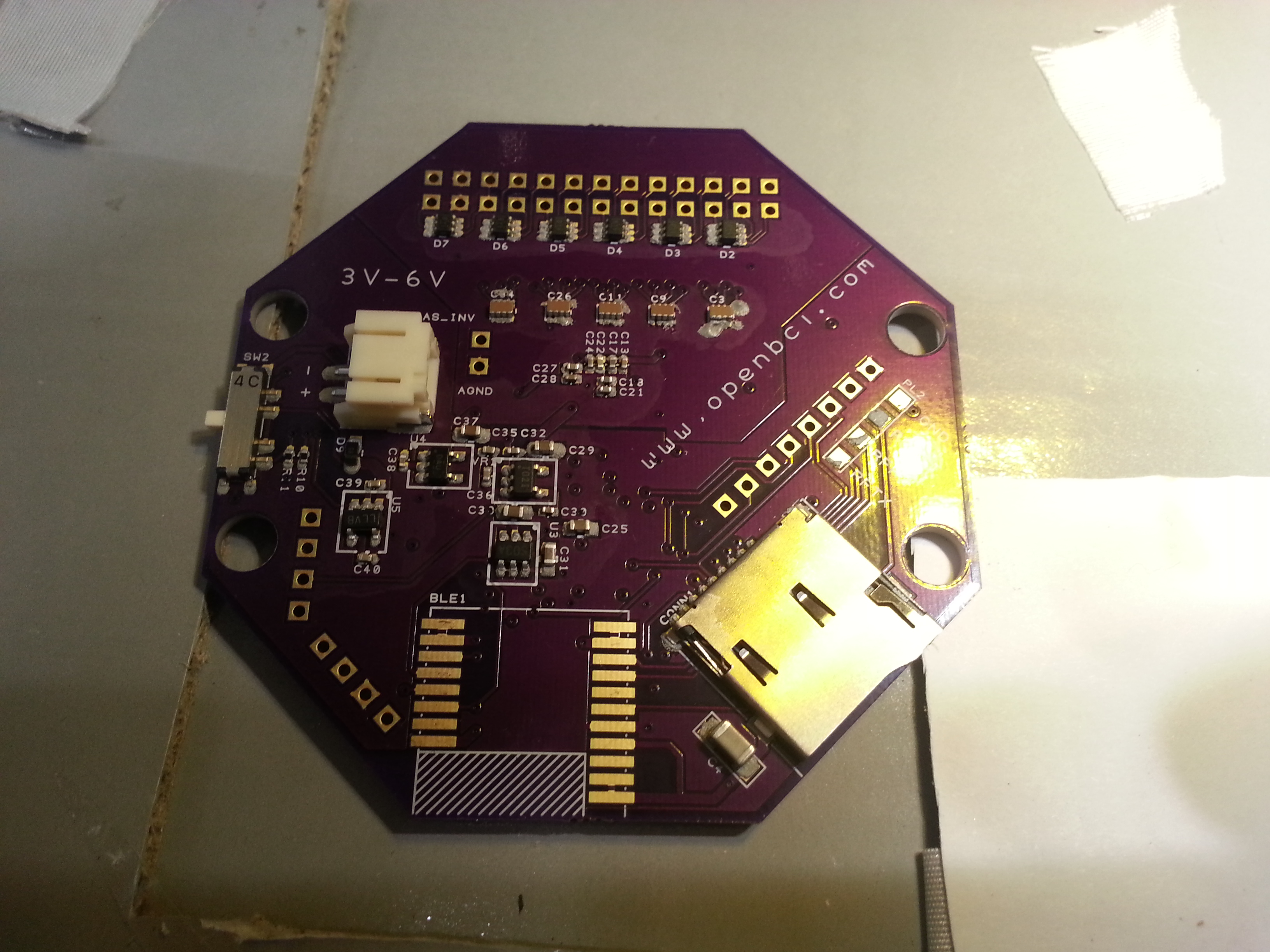
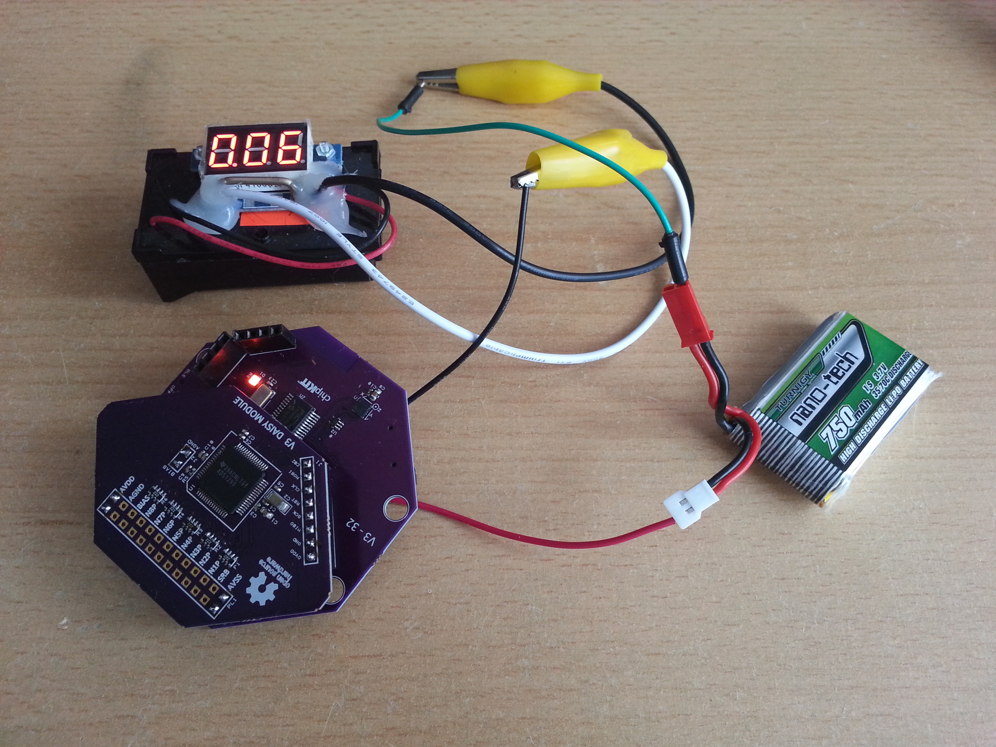
The current draw of the 32bit board is about 60 mA
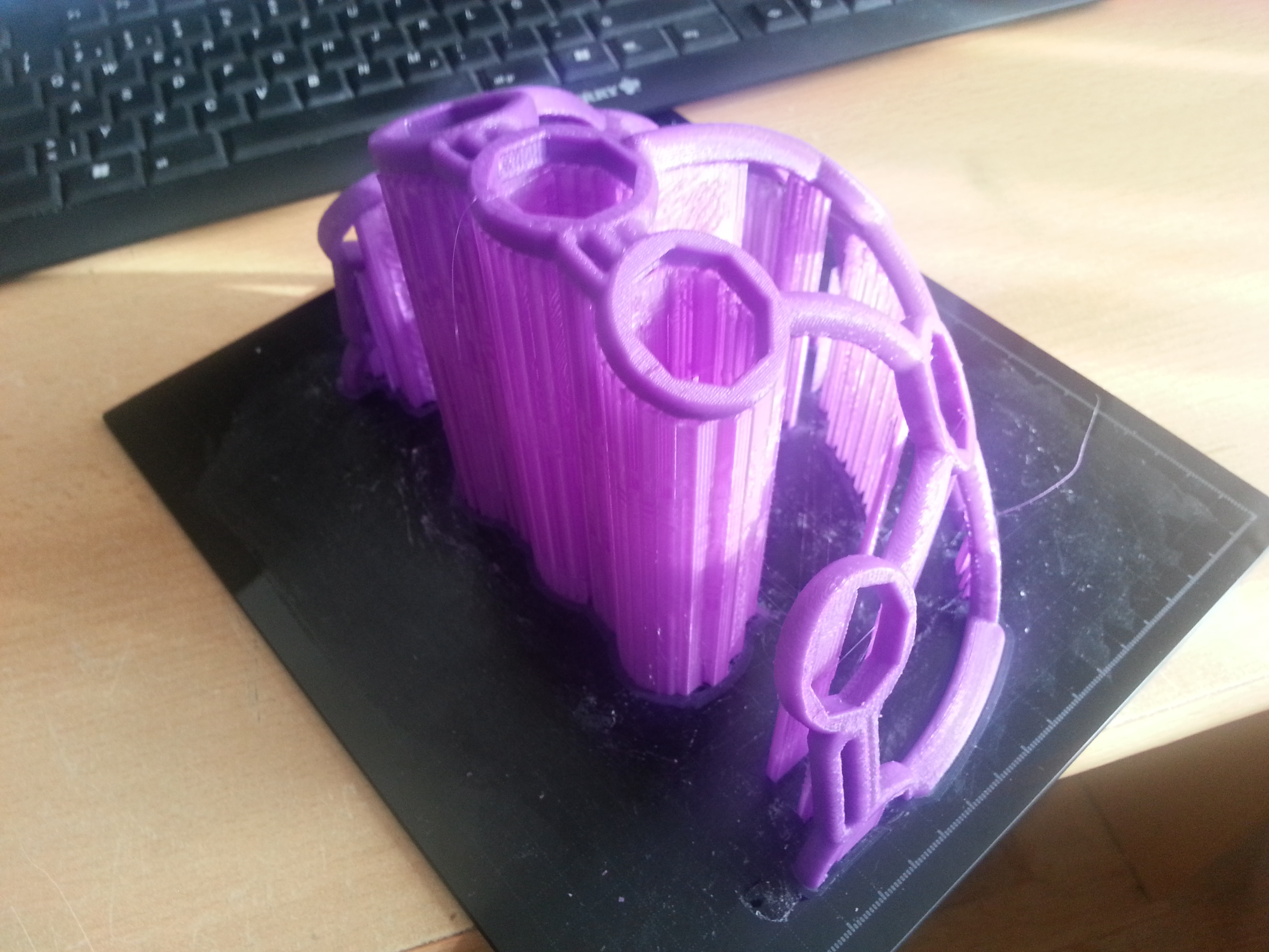
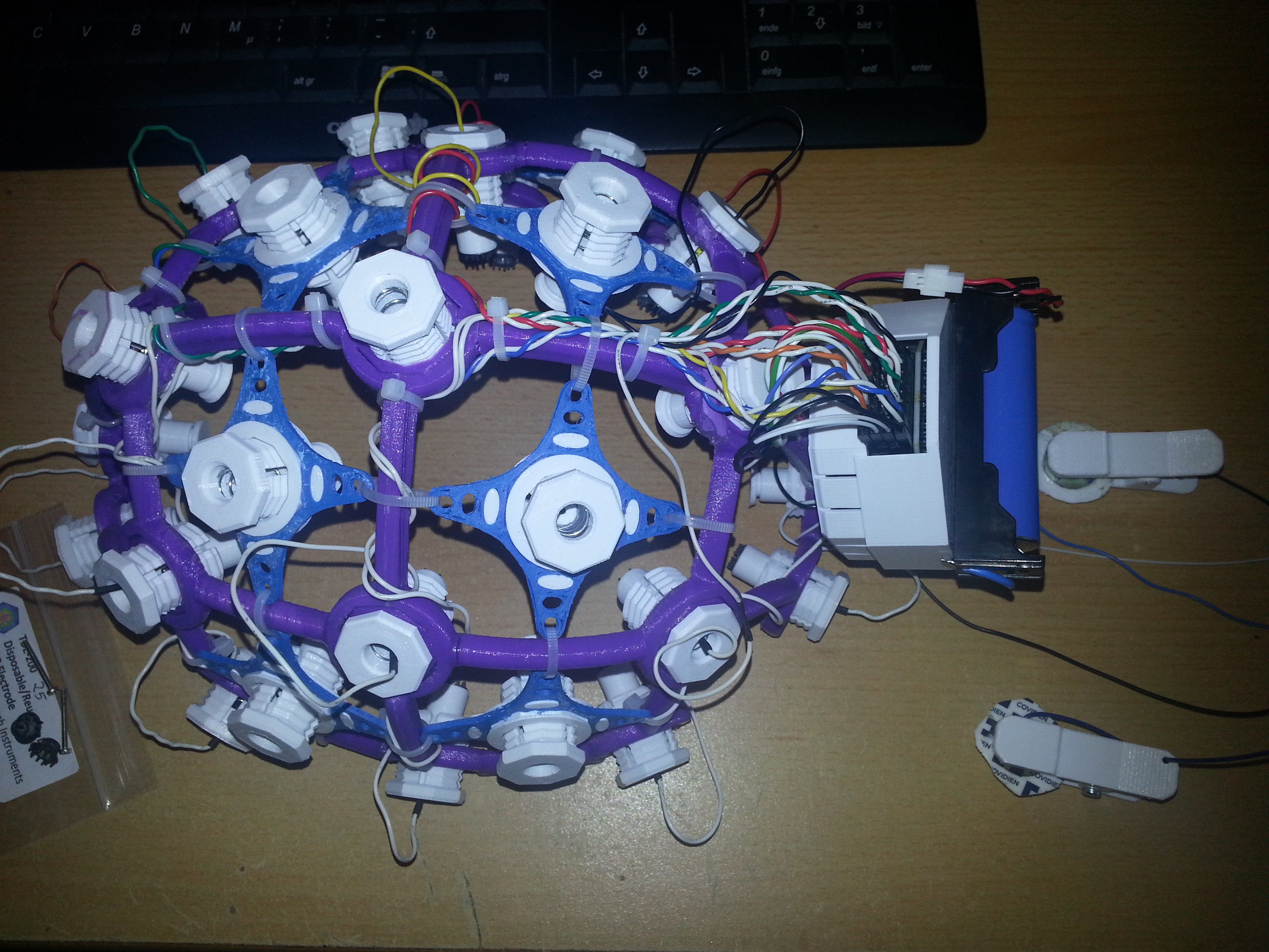
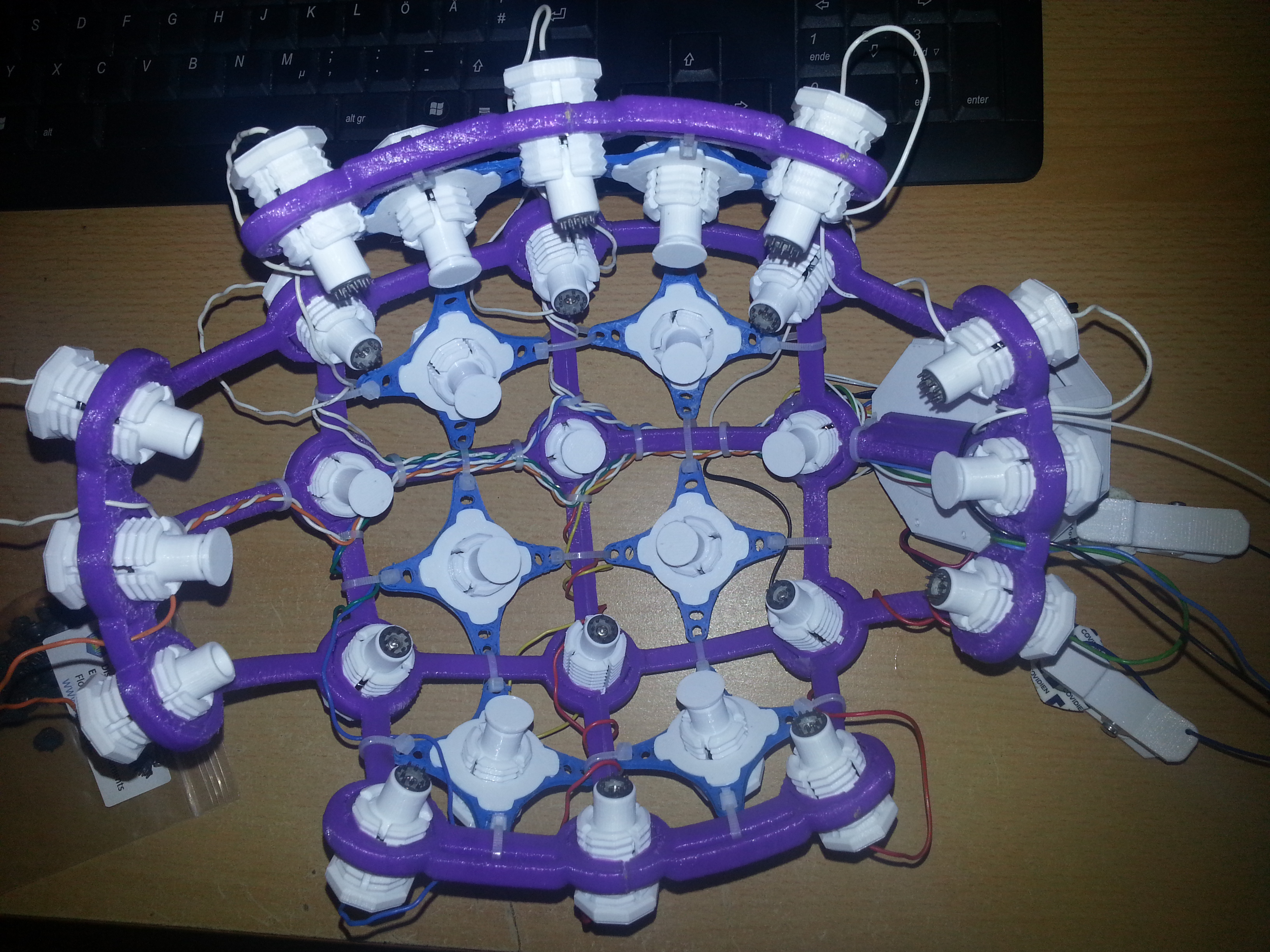
Time to print the headware (“Ultracortex Nova/Supernova”)
The print was done on an Ultimaker 2 clone with the recommended slicer settings and turned out ok. It took about 12 hours and I experienced some problems while printing the first half. Some parts snapped off because the print head collided with plastic that was bending up during cooldown. This happened only during a few layers of the print (approx after one third) because the structure was not stable enough at that stage. I could repair the broken parts by filling the defects with hot glue. When printing the second half I had an eye on the process and coud prevent that from happening.
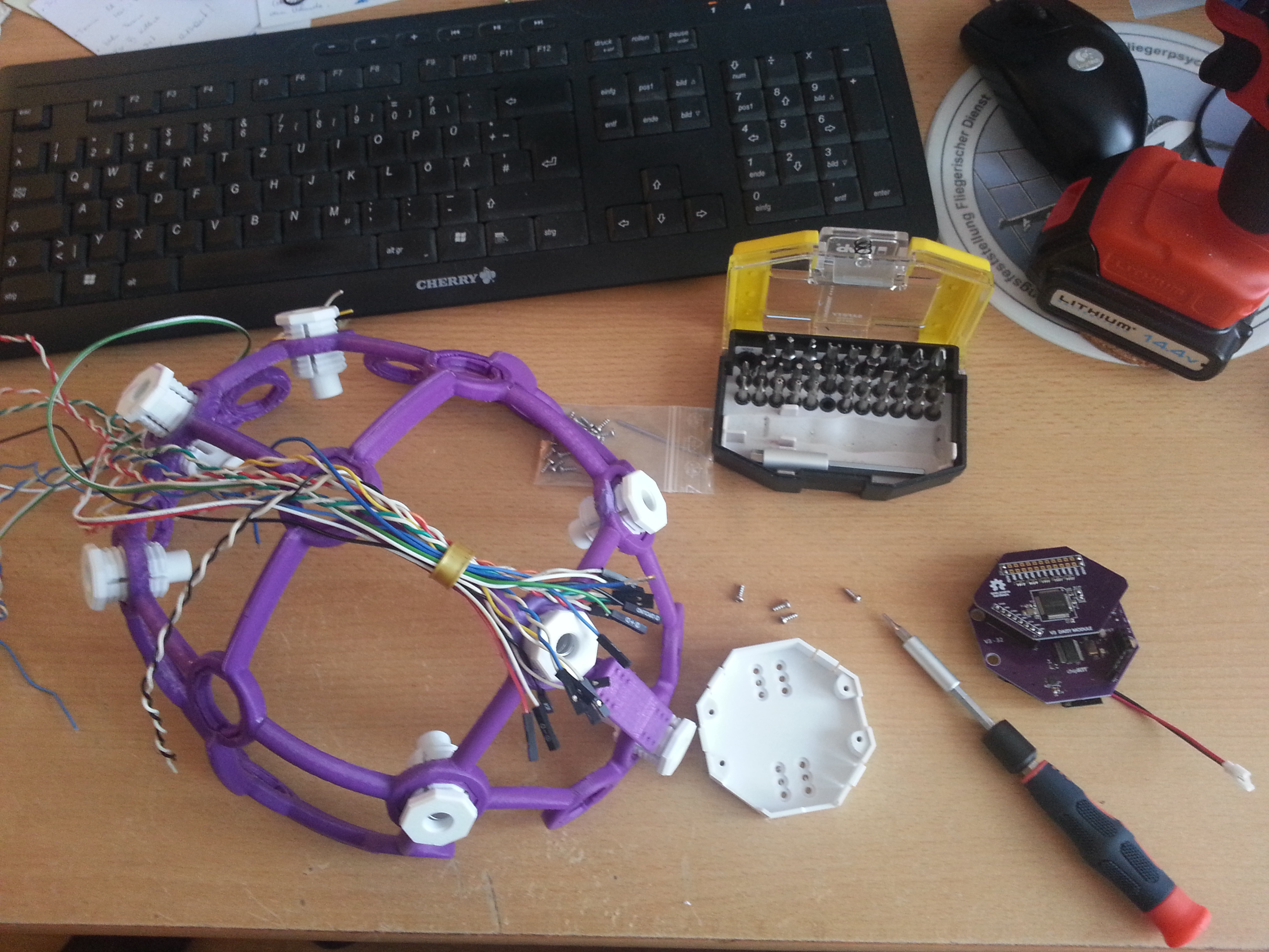
Used old PC tower cables to do the wiring. They were done in twisted pairs. All left electrodes are white and all right electrodes are colour-coded. That way you don’t need that many colors and nevertheless finding the corresponding electrode is easy.
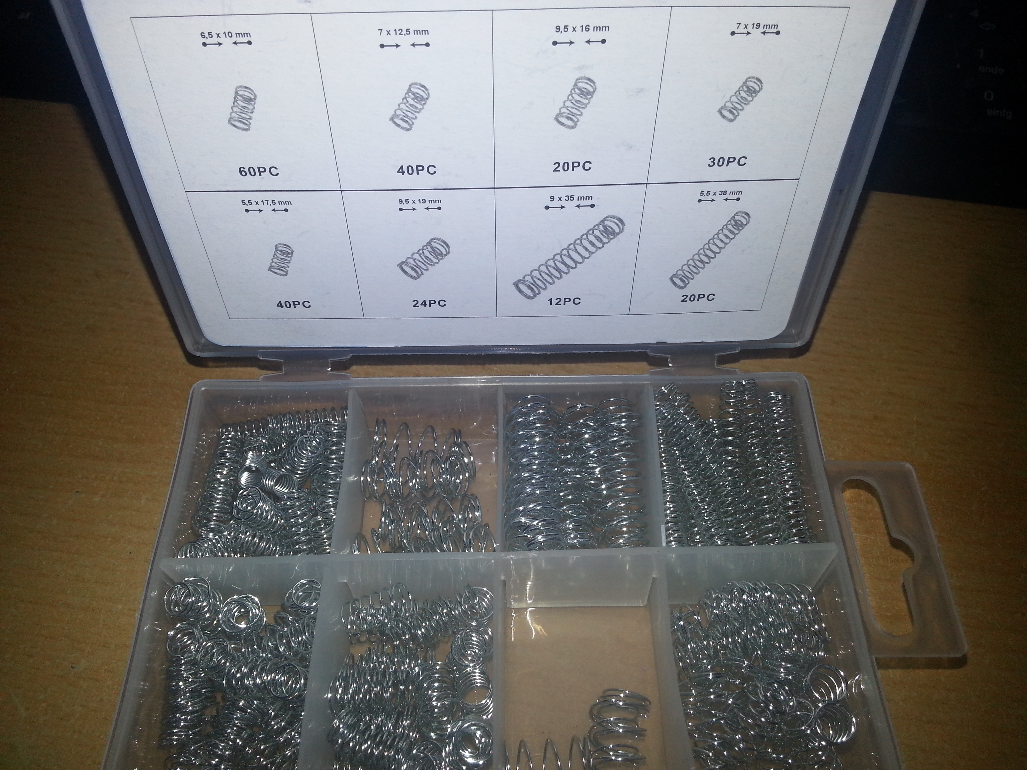
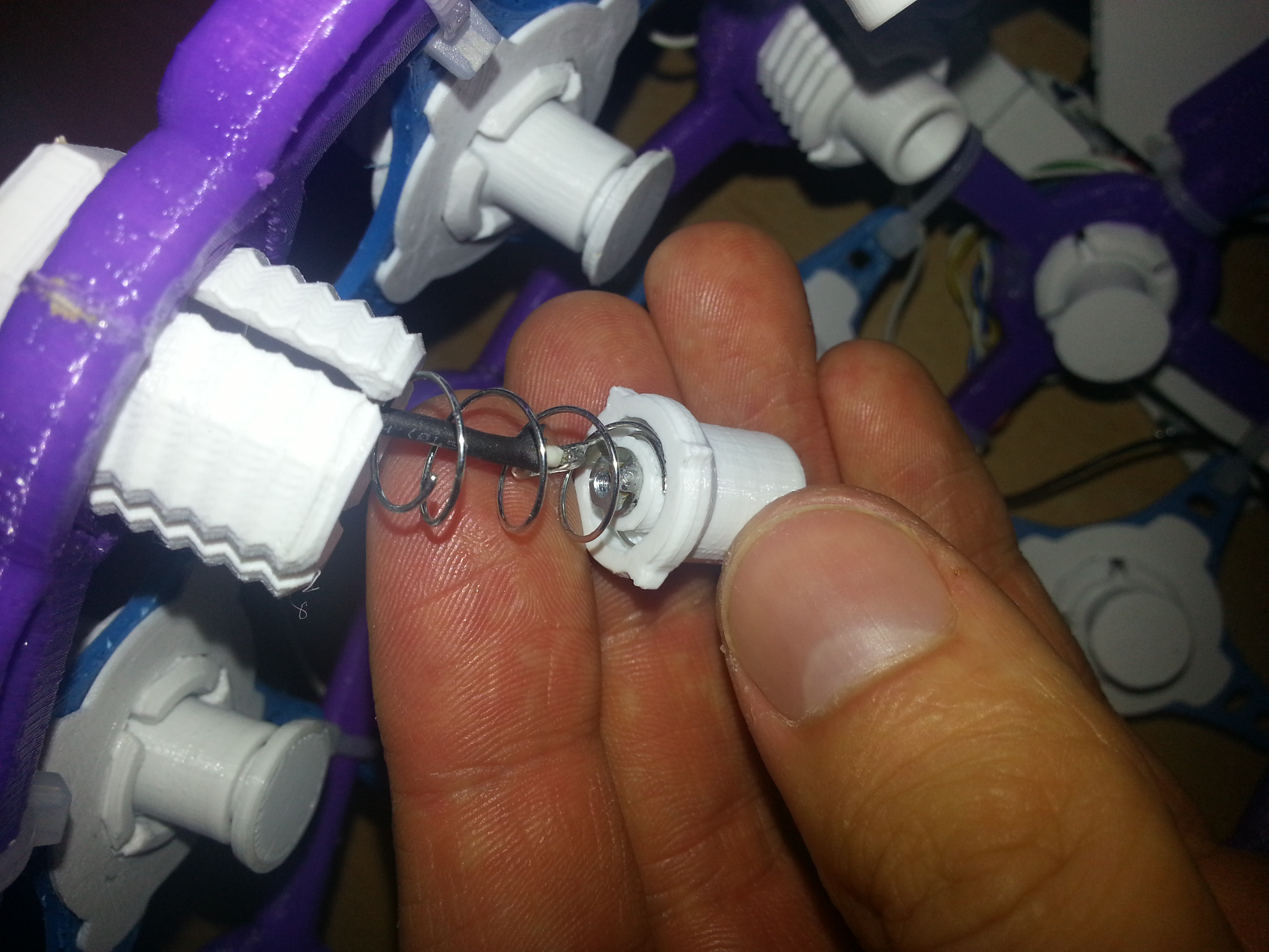
There are spring sets sold on the usual trading platform that contain the necessary springs to build the electrode inserts. The one below contains the “weak” as well as the “strong” spring for the “dummy inserts”. The weak spring had to be pulled apart a few mm to fit better.
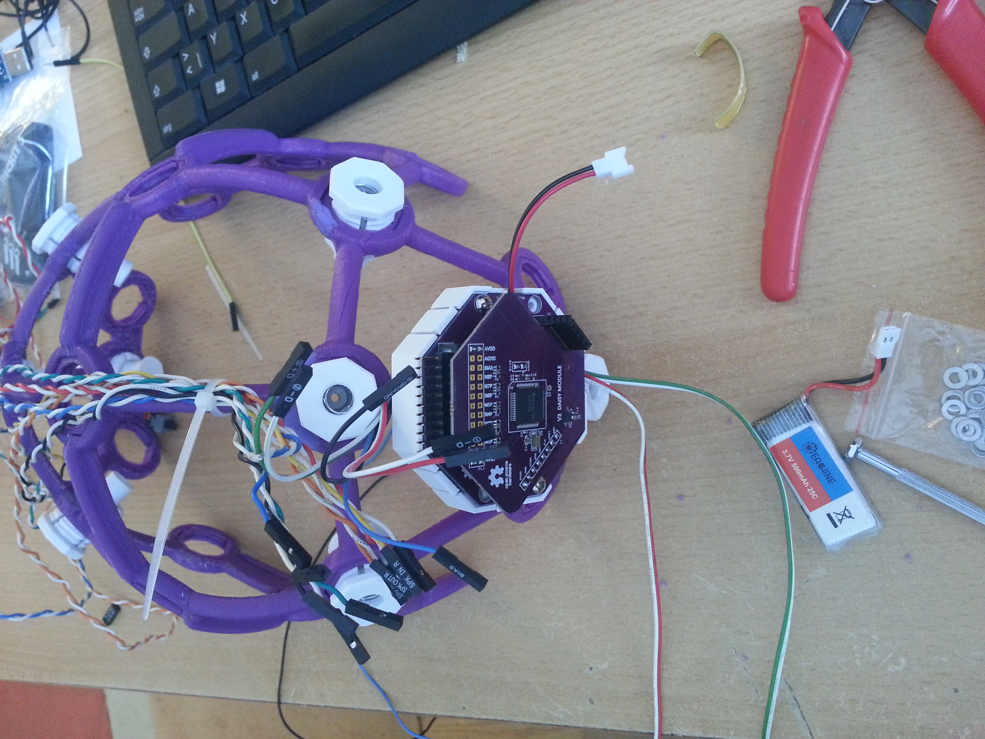

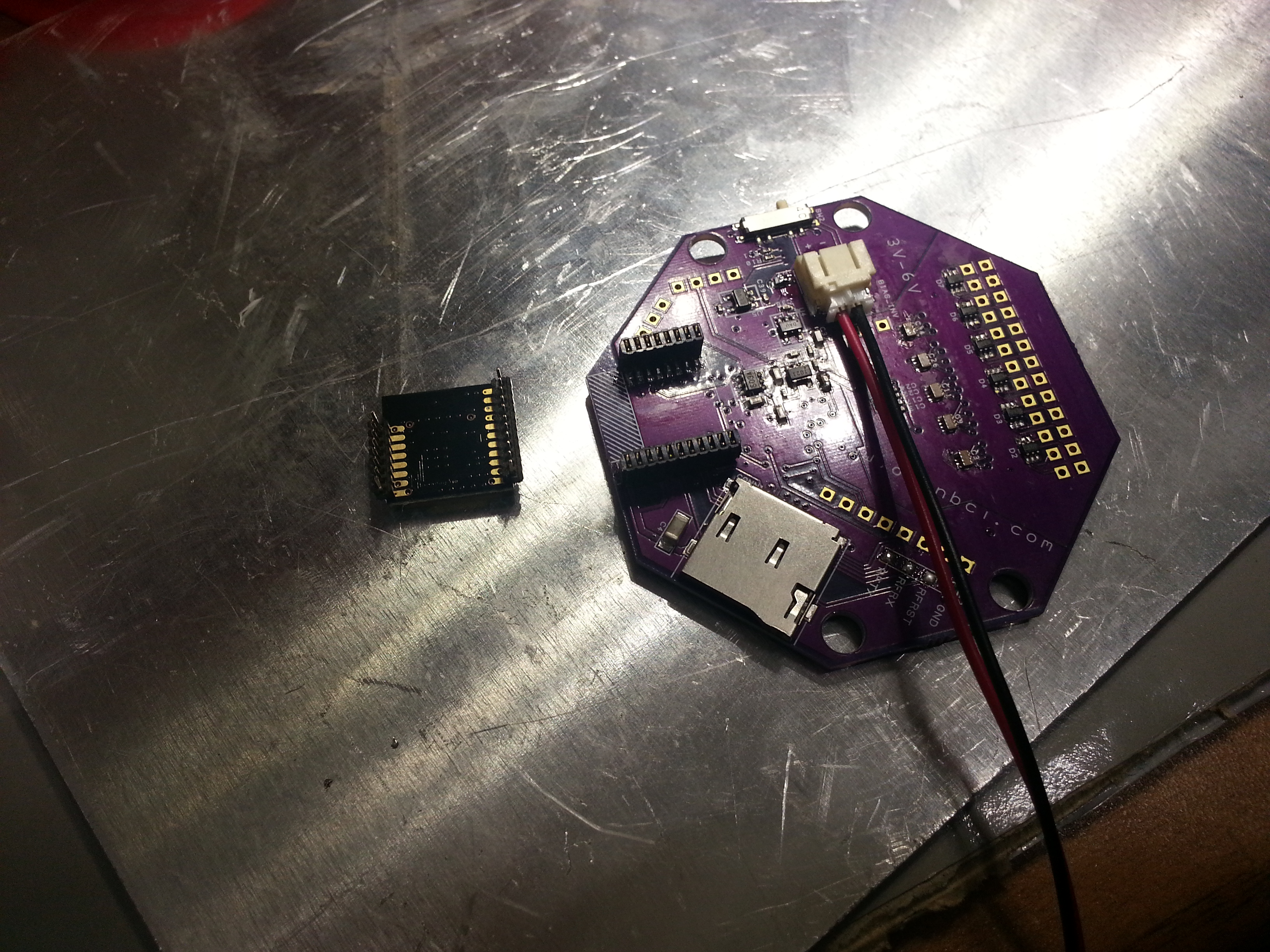
As you can see, I soldered the header of the Daisy board on the bottom side which takes up less space.
OpenBCI parts <–this zip file contains my snap-on lid design that also covers the Daisy board as well as the earclip electrode design. Both parts can be found on Thingiverse as well:
http://www.thingiverse.com/thing:1635759
http://www.thingiverse.com/thing:1648317

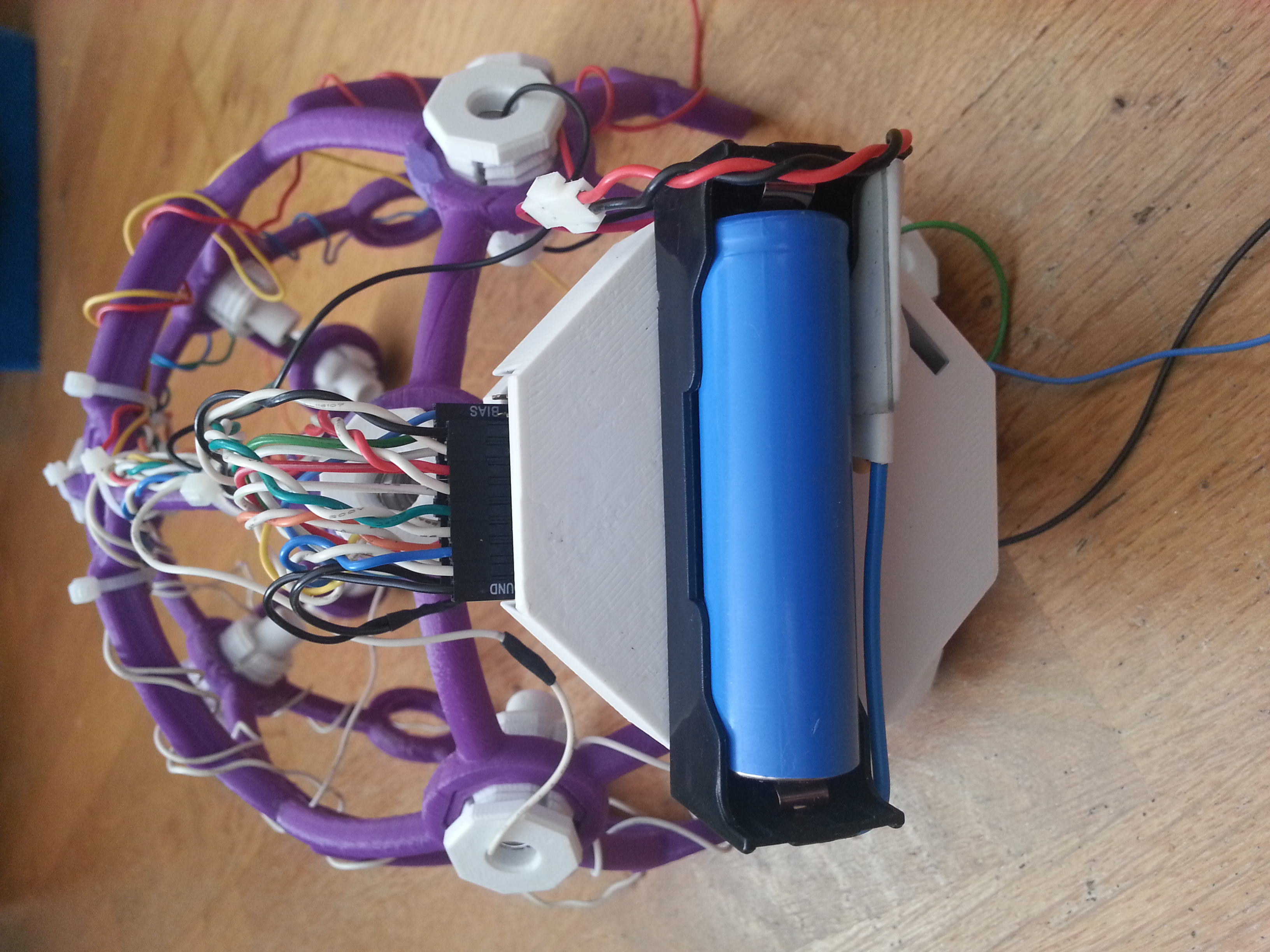
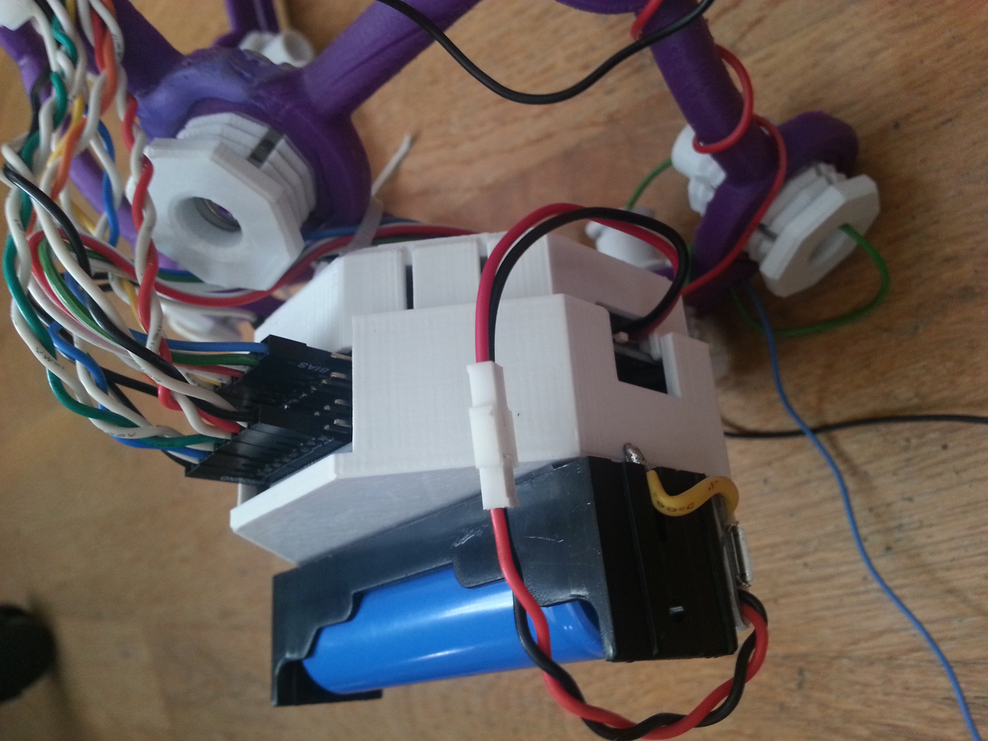
An 18650 holder with TP4056-based protection and charging circuit was placed on top to have a reliable power supply.
What you’re not being told: you have to print the “QUADSTAR” parts of the Ultracortex Nova/Supernova in PLA SOFT or any other elastomer filament. I had to modify my Prusa i3 extruder to prevent the soft 1.75 mm filament from kinking before entering into the bowden tube. This part fixes the issue: http://www.thingiverse.com/thing:1652091
Also I found that I had to turn off retractions because as soon as the filament passes the extruder drivewheel, it gets compressed and shoud not undergo this process twice because then it gets too damaged to be pushed into the bowden tube and extrusion simply stops at that point. Pain.
Finished Iron Maiden, err…. I mean Ultracortex, wired for the 16 channel standard configuration according to the Processing GUI with as many “comfy inserts” as possible.
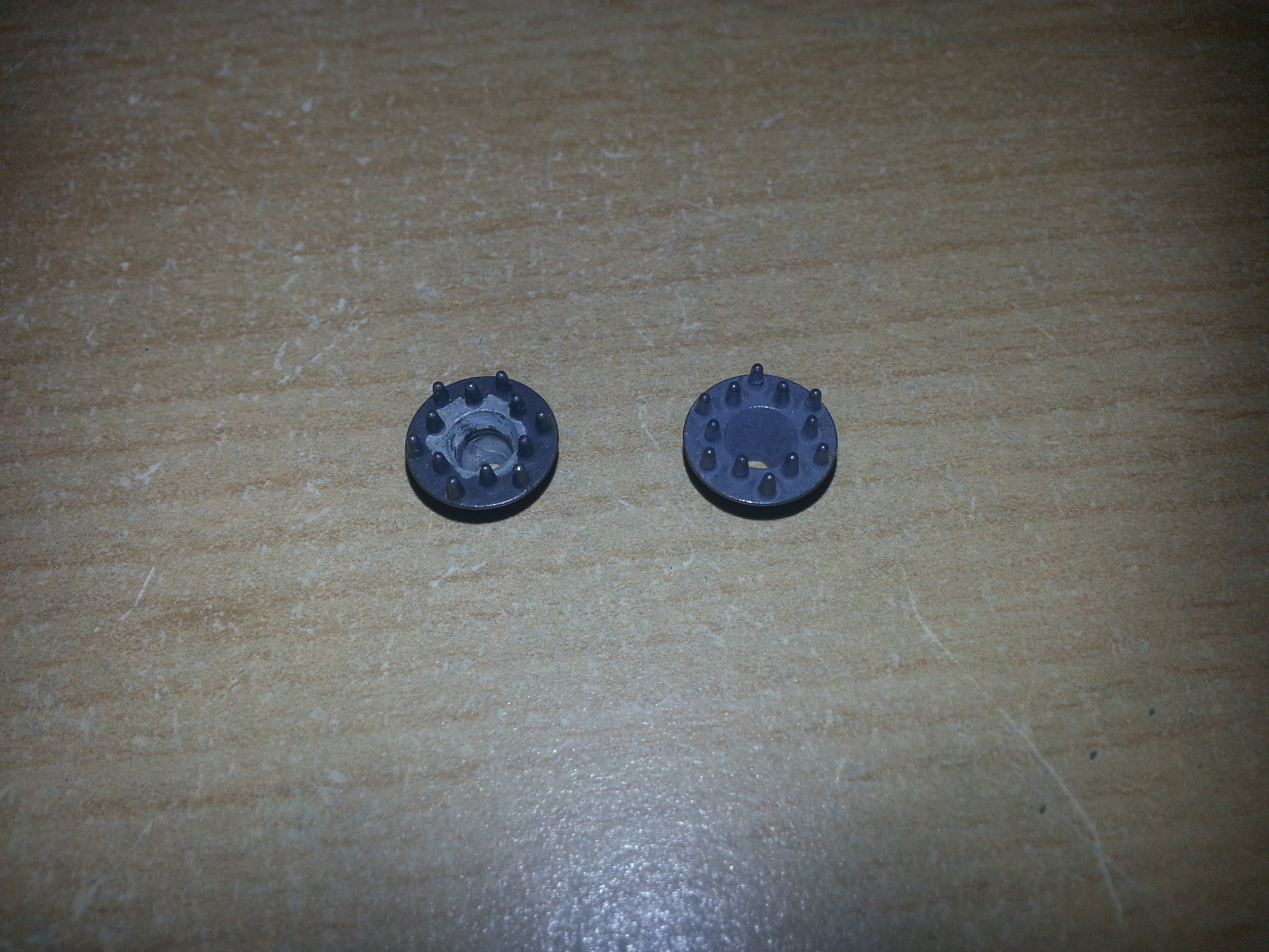
One thing I noticed after using the Disposable / Reusable Dry EEG Electrode [TDE-200] was instant corrosion. Not that surprising given that two different metals (stainless steel M2 bolt and Ag/AgCl surface) come in contact. As you can see on the picture below on the left electrode the AgCl layer corroded away to that extent after only one day. As a comparison there’s a fresh electrode on the right. The only solution I see at the moment is to attach the electrodes only if they are needed.
A slight modification was done to be able to add/remove electrodes more quickly: the electrode cables were soldered directly to the M2 nuts and superglued to the back of the electrode holder, so the nut stays attached to the plastic part even if there is no bolt pressing it down.
Results:
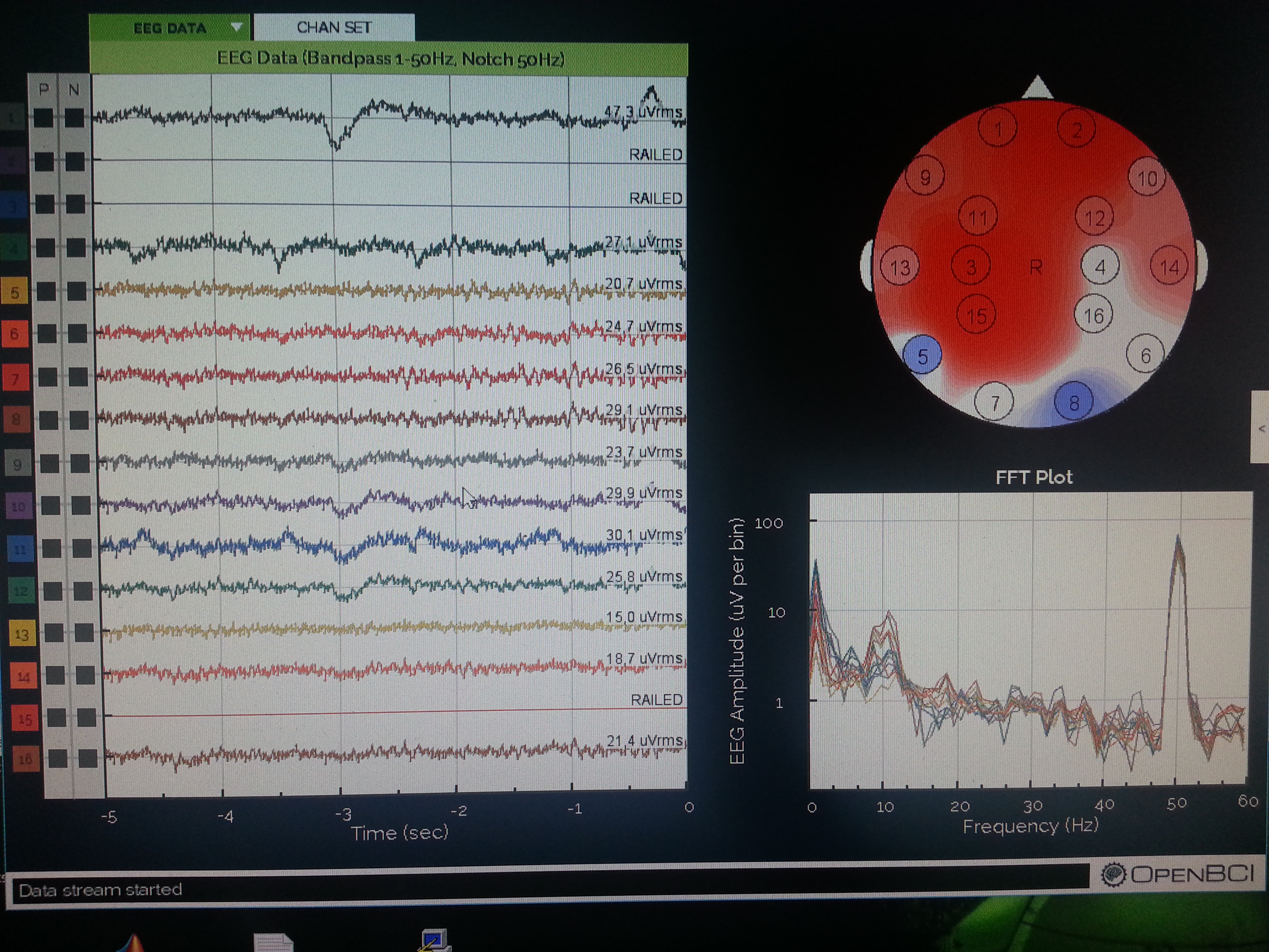
Rocording with my eyes closed. Note the alpha peak in the FFT plot. As you can see not all channels are working. It’s not that easy getting 16 dry electrodes to work. I’m also having issues with channel 2 for some reason. Maybe there’s a bad solder joint somewhere on the PCB.
Conclusions:
The OpenBCI V3 32bit + Daisy is a clean design and a good way to get 16 channels of electrophysiological data up and running and a great pplication for the ADS1299. The documentation is definitely good enough to build everything yourself, assuming you have some experience with SMT soldering. The DIY approach is also cheaper. I think you can get away with one third the price for the 32bit board and Daisy module, not including the cost of your labour of course. It’s a challenging project, but for me it was worth the effort. The DIY approach gives you the possibility to modify the design if you need to. I would like to use the potential of the ADS1299 more in the future and for example increase the sampling rate.
When it comes to the headware, my initial fascination faded a little when I discovered that the Ultracortex is quite painful to wear! The comb electrodes are no pleasure on your skin, let me tell you! But they do provide good signal quality almost instantaneously. The corrosion issue is also a significant one. I’m wondering how the signal quality changes as soon as the AgCl layer is gone completely. Maybe there’s a way of re-applying the layer by electrolysis in NaCl solution. This remains subject of further investigation. Other that those insights I find the design of the Ultracortex amazing! It’s a perfect example of great design specifically for 3D printing. Everything fits together perfectly well and looks great! Many thanks to the OpenBCI team for making their great work open source!
Hey mate!
I know there’s the BOM on the OpenBCI docs though some of the capacitors/resistors don’t have tolerances etc and it seems a bit incomplete.
Any chance you’d be able to upload the items/BOM that you used?
Thank you,
Oliver
Hey, my BOM is not the best example. Somewhere in the documentation ist says: all caps are ceramic x7r and all resistors 1%. I’ve partially chosen caps that are x5r and 5% resistors. So I think Rs and Cs should not be a problem.
Good luck with the build
Good one !! I am trying to build it too 😀
Hi Kauz,
Not sure if you have any pointers, though i’ve flashed my boot loader with Pickit, though when i then try to upload the actual code i can’t enter boot loader mode. I’m pressing the correct prog/reset combinations, though my blue LED just doesn’t light up. I’ve verified voltages on the PIC32, and I’m fairly stuck with where to go next.
Did you upload the actual OpenBCI code with the Pickit? or did you upload it over Bluetooth like the OpenBCI docs suggest?
Thank you
Jason
Hi Jason,
I’ve uploaded the actual OpenBCI code via wireless (it’s not really Bluetooth, the protocol the OpenBCI folks have implemented there is called GZLL). The wireless module is connected to the PIC via UART (TXD and RXD) and in bootloader mode the PIC is expecting its program code via UART. So if you lack wireless modules you can connect a USB-Serial chip and use that.
I hope this was helpful.
Arthur
Hi Kauz!
This construction is fine!
I want to repeat it. I am interesting how work my brain and how it make to do better and effectivity. I am from Russia and speak English very weak. Where are you get firmware and soft for it?
Hi,
the project is called OpenBCI, it’s well-documented
http://docs.openbci.com/Getting%20Started/00-Welcome
The firmware and software is on github
https://github.com/OpenBCI
excellent work @kauz. I am also planning to make the OpenBCI 32-bit board. I was searching for the sm0603 and EIA_0402 packages of capacitors on Mouser and got confused. Is it required to order the exact packages or can i just order MLCC X7R capacitors of the given values?
Thanks! Oh the packages are just 0603 and 0402, which is just the dimensions of the part. Meaning that for example 0603 is .06 x .03 inches big. Caps and resistors should have the right value and tolerance. In the case of resistors it’s 1% and in the case of all the multilayer ceramic capacitors it’s “X7R” (which is the temperature coefficient). That’s all you need. Those 3 values are standard ones and you get them almost everywhere.
Thank you for responding @kauz. I wanted to make sure whether the packages mentioned are in inches or mm. Thank you for guiding 🙂
Which company made its pcb boards?
Good old OSH Park
hi dear Kauz
i want to build openbci 32 bit
i send gerber file to pcb factory
no i search and buy the component
i find every thing ,but i cant find rfd22301
what can i do?which module replace it? is it possible to connect cyton to laptop without doungle?
thank you
regard