
As a medical professional I’ve always been interested in experimenting with biosignals. I’ve made a couple of attempts to build the analog part of a simple ECG amplifier, but encountered some obstacles. Some day I’ve found this well-designed ECG/EMG shield by Olimex which uses an instrumentation amplifier and fits on an Arduino board. It comes with some sample code as well. I was suprised that it uses old C commands such as cbi, sbi, outp() and inp() but I learned a lot while going through the code and understanding it. It was originally written to interface with the ElectricGuru EEG-software via the serial port and processes the input signal of up to 6 of those shields, since they can be stacked together easily.
First of all I wanted to play with the ECG signal and since I had just figured out how to use a KS0108 GLCD, I just combined both to make this neat biofeedback device. One obstacle I came across when trying to connect the LCD to a microcontroller is figuring out which model it is! So take a look at the data sheet or whatever, because there are 3 types of those 20pin displays! The glcd library documentation on contains a table that visualizes the pinouts. Because there are many wires you have to mess around with, I simply soldered a female header on a Proto Shield and hard wired everything.
Another function I wanted to implement is QRS-detection. QRS complexes are those pointed, high spikes in an ECG which represent the electrical activity in the main muscular mass of the heart (myocardium). Their detection is quite easy by measuring the biggest slopes and and can give a more or less reliable representation of one cycle of cardial action. My code calculates the time between 2 detected “heartbeats” (RR interval) and displays that as the heart rate. This has the advantage over averaging a couple of heartbeats that you can directly observe how your heartbeats vary.
Many interestings things can be done with this kind of setup. The next step will be logging the ECG by either writing it to a SD card or sending the data to a PC via bluetooth and logging there (patient insulation from mains powered devices and less disturbing influence from the mains line). This is a very powerful tool for diagnostic purposes. For example arrythmias that occur under certain circumstances can be diagnosed or heart rate variability can be measured, which can give you information on the influence of the autonomic nervous system on cardial action…
Interrupt-based code, modified for use with the glcd:
/**********************************************************/
/* Demo program for:                                      */
/*    Board: SHIELD-EKG/EMG + Olimexino328                */
/*  Manufacture: OLIMEX                                   */
/*  COPYRIGHT (C) 2012                                    */
/*  Designed by:  Penko Todorov Bozhkov                   */
/*   Module Name:   Sketch                                */
/*   File   Name:   ShieldEkgEmgDemo.pde                  */
/*   Revision:  initial                                   */
/*   Date: 01.02.2012                                     */
/*   Built with Arduino C/C++ Compiler, version: 1.0      */

/*EXTENDED BY insanity wolf */

/*This version is for monitoring the signal directly on a KS0108 graphical LCD display*/

/**********************************************************/
/**********************************************************
Purpose of this programme is to give you an easy way to
connect Olimexino328 to ElectricGuru(TM), see:
http://www.realization.org/page/topics/electric_guru.htm
where you'll be able to observe yours own EKG or EMG signal.
It is based on:
***********************************************************
* ModularEEG firmware for one-way transmission, v0.5.4-p2
* Copyright (c) 2002-2003, Joerg Hansmann, Jim Peters, Andreas Robinson
* License: GNU General Public License (GPL) v2
***********************************************************
For proper communication packet format given below have to be supported:
///////////////////////////////////////////////
////////// Packet Format Version 2 ////////////
///////////////////////////////////////////////
// 17-byte packets are transmitted from Olimexino328 at 256Hz,
// using 1 start bit, 8 data bits, 1 stop bit, no parity, 57600 bits per second.

// Minimial transmission speed is 256Hz * sizeof(Olimexino328_packet) * 10 = 43520 bps.

struct Olimexino328_packet
{
  uint8_t    sync0;        // = 0xa5
  uint8_t    sync1;        // = 0x5a
  uint8_t    version;    // = 2 (packet version)
  uint8_t    count;        // packet counter. Increases by 1 each packet.
  uint16_t    data[6];    // 10-bit sample (= 0 - 1023) in big endian (Motorola) format.
  uint8_t    switches;    // State of PD5 to PD2, in bits 3 to 0.
};
*/
/**********************************************************/
#include <glcd.h>
//http://www.arduino.cc/playground/Code/GLCDks0108

#include "fonts/allFonts.h"         // system and arial14 fonts are used
#include "bitmaps/allBitmaps.h"       // all images in the bitmap dir
gText textArea;              // a text area to be defined later in the sketch


#include <compat/deprecated.h>
#include <FlexiTimer2.h>
//http://www.arduino.cc/playground/Main/FlexiTimer2
#include <TimerOne.h>
//http://arduino.cc/playground/Code/Timer1

/*
Erklärung von cbi, sbi, outp und inp
Bei solchen Makros sollte man etwas mehr Klammern spendieren:

#define sbi(ADDRESS,BIT) ((ADDRESS) |= (1<<(BIT)))
#define cbi(ADDRESS,BIT) ((ADDRESS) &= ~(1<<(BIT)))
#define outp(VAL,ADRESS) ((ADRESS) = (VAL))
#define inp(VAL) (VAL)
The outb( ) function provides a C language interface to the machine instruction that writes a byte to an 8 bit I/O port using the I/O address space instead of the memory address space.
*/

// All definitions
#define NUMCHANNELS 6
#define HEADERLEN 4
#define PACKETLEN (NUMCHANNELS * 2 + HEADERLEN + 1)    //6*2+4+1
#define SAMPFREQ 256                   // ADC sampling rate 256
#define TIMER2VAL (1024/(SAMPFREQ))    // Set 256Hz sampling frequency
#define PWM_OUT 9                      // Number of pin used for generating CAL_SIG
#define PWMFREQ 10        //10Hz for Calibration signal
#define LED1  13

// Global constants and variables
char const channel_order[]= { 0, 1, 2, 3, 4, 5 };
volatile unsigned char TXBuf[PACKETLEN];  //The transmission packet
volatile unsigned char TXIndex;           //Next byte to write in the transmission packet.
volatile unsigned char CurrentCh;         //Current channel being sampled.

//~~~~~~~~~~
// Functions
//~~~~~~~~~~

/****************************************************/
/*  Function name: Toggle_LED1                      */
/*  Parameters                                      */
/*    Input   :  No                                */
/*    Output  :  No                                 */
/*    Action: Switches-over LED1.                   */
/****************************************************/
void Toggle_LED1(void){

 if((digitalRead(LED1))==HIGH){
   digitalWrite(LED1,LOW);
  }
  else{
   digitalWrite(LED1,HIGH);
  }
}

/****************************************************/
/*  Function name: setup                            */
/*  Parameters                                      */
/*    Input   :  No                                */
/*    Output  :  No                                 */
/*    Action: Initializes all peripherals           */
/****************************************************/
void setup() {

 noInterrupts();  // Disable all interrupts before initialization

 // LED1
 pinMode(LED1, OUTPUT);  //Setup LED1 direction
 digitalWrite(LED1,LOW); //Setup LED1 state

 //Write packet header and footer
 TXBuf[0] = 0xa5;  //Sync 0
 TXBuf[1] = 0x5a;  //Sync 1
 TXBuf[2] = 2;     //Protocol version
 TXBuf[3] = 0;     //Packet counter

 // ADC
 // Timings for sampling of one 10-bit AD-value:
 // XTAL = 16000000MHz
 // prescaler > ((XTAL / 200kHz) = 80 =>
 // prescaler = 128 (ADPS2 = 1, ADPS1 = 1, ADPS0 = 1)
 // ADCYCLE = XTAL / prescaler = 125000Hz or 8 us/cycle
 // 14 (single conversion) cycles = 112 us
 // 26 (1st conversion) cycles = 208 us
 outb(ADMUX, 0);         //Select channel 0
 outb(ADCSRA, ((1<<ADPS2) | (1<<ADPS1)| (1<<ADPS0))); //Prescaler = 128, free running mode = off, interrupts off.
 sbi(ADCSRA, ADIF);  //Reset any pending ADC interrupts
 sbi(ADCSRA, ADEN);  //Enable the ADC

 // Serial Port
 outb(UBRR0, 16);              //Set speed to 57600 bps
 outb(UCSR0B, (1<<TXEN0));     //Enable USART Transmitter.

 // Timer1
 // It's used for calibration signal generation: CAL_SIG via PWM.
 // CAL_SIG is used like reference signal when setting-up SHIELD-EKG/EMG's channel gain
 // During normal operation this signal is not required so it can be disabled with uncommenting te row below!
 /*
 pinMode(PWM_OUT, OUTPUT);    //Set PWM_OUT direction
 digitalWrite(PWM_OUT,LOW);   //Set PWM_OUT state
 Timer1.initialize((1000000/(PWMFREQ))); // initialize timer1, and set a 1/10 second period = 10Hz ->freq. of cal signal should be 10-14Hz (schematic)
 Timer1.pwm(PWM_OUT, 512);             // setup pwm on pin 9, 50% duty cycle
 //Timer1.disablePwm(PWM_OUT); // Uncomment if CAL_SIG is not requiered
 */

 // Timer2
 // Timer2 is used for setting ADC sampling frequency.

/*****************************************************************
Methods of the FlexiTimer2 library:

FlexiTimer2::set(unsigned long units, double resolution, void (*f)())
    this function sets a time on units time the resolution for the overflow. Each overflow, "f" will be called. "f" has to be declared void with no parameters.
    E.g. units=1, resolution = 1.0/3000 will call f 3000 times per second, whereas it would be called only 1500 times per second when units=2.
FlexiTimer2::set(unsigned long ms, void (*f)())
    this function sets a time on ms (1/1000th of a second) for the overflow. Each overflow, "f" will be called. "f" has to be declared void with no parameters.
    Shorthand for calling the function above with resolution = 0.001.
FlexiTimer2::start()
    enables the interrupt.
FlexiTimer2::stop()
    disables the interrupt.
*******************************************************************/
 FlexiTimer2::set(TIMER2VAL, Timer2_Overflow_ISR); //TIMER2VAL was (1024/(SAMPFREQ)) in ms =4, SAMPLEFREQ was 256
 FlexiTimer2::start();  //enable the Interrupt....

 // MCU sleep mode = idle.
 outb(MCUCR,(inp(MCUCR) | (1<<SE)) & (~(1<<SM0) | ~(1<<SM1) | ~(1<<SM2)));

 interrupts();  // Enable all interrupts after initialization has been completed

 GLCD.Init();
 GLCD.SelectFont(System5x7, BLACK); // font for the default text area
}

/****************************************************/
/*  Function name: Timer2_Overflow_ISR              */
/*  Parameters                                      */
/*    Input   :  No                                */
/*    Output  :  No                                 */
/*    Action: Determines ADC sampling frequency.    */
/****************************************************/
void Timer2_Overflow_ISR()    //alle 4ms wird das ausgeführt
{
  // Toggle LED1 with ADC sampling frequency /2
  Toggle_LED1();

  CurrentCh = 0;
  // Write header and footer:
  // Increase packet counter (fourth byte in header)
   //Write packet header and footer
 /**********zur Erinnerung: der Header**********
 TXBuf[0] = 0xa5;  //Sync 0
 TXBuf[1] = 0x5a;  //Sync 1
 TXBuf[2] = 2;     //Protocol version
 TXBuf[3] = 0;     //Packet counter
 ***********************************/
 TXBuf[3]++;
  //the whole packet is /6*2+4+1=17byte
  //Get state of switches on PD2..5, if any (last byte in packet).
  TXBuf[2 * NUMCHANNELS + HEADERLEN] = (inp(PIND) >> 2) &0x0F;  //2* NUMCHANNELS, weil jeder CHannel 2 byte hat damit 1024 reinpasst

  cbi(UCSR0B, UDRIE0); //Ensure Data Register Empty Interrupt is disabled.
  sbi(ADCSRA, ADIF);   //Reset any pending ADC interrupts
  sbi(ADCSRA, ADIE);   //Enable ADC interrupts.
  sbi(ADCSRA, ADSC) ;  // Start conversion!!!
  //Next interrupt will be ISR(ADC_vect)
}

/****************************************************/
/*  Function name: ISR(ADC_vect)                    */
/*  Parameters                                      */
/*    Input   :  No                                */
/*    Output  :  No                                 */
/*    Action: Reads ADC's current selected channel  */
/*            and stores its value into TXBuf. When */
/*            TXBuf is full, it starts sending.     */
/****************************************************/
ISR(ADC_vect)
{
 volatile unsigned char i;    //volatile??

 i = 2 * CurrentCh + HEADERLEN;  //also wird i auf 4 gesetzt wenn CurrentCh==0 und unten das 5. byte beschrieben,danach TxBuf[4] ([3] ist das letzte vom Header)
 TXBuf[i+1] = inp(ADCL);      //ADC data register LOW byte
 TXBuf[i] = inp(ADCH);        //ADC data register HIGH byte
 CurrentCh++;
 if (CurrentCh < NUMCHANNELS)
 {
  outb(ADMUX, (channel_order[CurrentCh])); //Select the next channel.
  sbi(ADCSRA, ADSC) ;                   //Start conversion!!! (set ADSC-bit in ADCSRA-Register)
 }
 else
 {
   //this gets executed first....prior to the stuff above
  outb(ADMUX, channel_order[0]);      //Prepare next conversion, on channel 0.
  cbi(ADCSRA, ADIE);    //Disable ADC interrupts to prevent further calls to ISR(ADC_vect). oben hiess es sbi!!!!!!
  outb(UDR0, TXBuf[0]); //Send first Packet's byte: Sync 0
  sbi(UCSR0B, UDRIE0);  //USART Data Register Empty Interrupt Enable
  TXIndex = 1;          //Next interrupt will be ISR(USART_UDRE_vect)
 }
}

/****************************************************/
/*  Function name: ISR(USART_UDRE_vect)             */
/*  Parameters                                      */
/*    Input   :  No                                */
/*    Output  :  No                                 */
/*    Action: Sends remaining part of the Packet.   */
/****************************************************/
ISR(USART_UDRE_vect){

 outb(UDR0, TXBuf[TXIndex]);  //Send next byte
 TXIndex++;
 /******hier also***
 ch0hb = TxBuf[4];
 ch0lb = TxBuf[5];
 *******************/


 if (TXIndex == PACKETLEN)    //See if we're done with this packet
 {
   cbi(UCSR0B, UDRIE0);    //USART Data Register Empty Interrupt Disable
                              //Next interrupt will be Timer2_Overflow_ISR()
 }
}


//function for fusion of the ADCL and ADCH byte

unsigned int weiterverarbeitung(volatile unsigned char high_byte, volatile unsigned char low_byte)
{
 unsigned int value = ((high_byte&0x0f)*256)+(low_byte);
 return(value);
}

/****************************************************/
/*  Function name: loop                             */
/*  Parameters                                      */
/*    Input   :  last 2 channel bytes of the packet */
/*    Output  :  to display                         */
/*    Action: Draws ECG, detects QRS, calculates HR */
/****************************************************/
unsigned long Start, Finished = 0;
float heart_rate = 0.0;
float RR_interval = 0.0;
unsigned int Delay = 9;
int thisdot = 0;
int prevdot = 0;


void loop() {


  for(int i=0; i<GLCD.Width; i++)
  {

    Finished = 0;
    unsigned int val = weiterverarbeitung(TXBuf[14],TXBuf[15]);  //using A5 and extracting the last 2 channel bytes out of the packet
    unsigned int y = map (val, 0, 1023, 64, 0);      //oben=0!!
    thisdot = y;

    //slope can be negative so it has to be an SIGNED int
    int slope = prevdot - thisdot;

     if (slope >= 8 && Start == 0)
      {
        Start = millis();
      }
      else if(slope >= 8 && Start > 0)
    {

      Finished = millis();
        RR_interval = Finished - Start;

      if(RR_interval>=150)  //refractory period
        {
          RR_interval = RR_interval/1000;  //convert to seconds
          heart_rate = 60/RR_interval;

        }

      Start = 0;

    }


          if(heart_rate<220)
              {
              GLCD.CursorToXY(GLCD.CenterX, 2);
              GLCD.print(heart_rate);

              }


    //Draw graph
    GLCD.SetDot(i,y,BLACK);
    delay(Delay);

    prevdot = thisdot;
    thisdot = 0;
    slope = 0;

  }


GLCD.ClearScreen();

}
In the code window below you can see the simple version of the code which is only suitable for visualization on the glcd and has an inconstant sampling rate since it reads the ADC from the main loop.
/**********************************************************/
//Simple ECG monitor program
/**********************************************************/
#include <glcd.h>
//http://www.arduino.cc/playground/Code/GLCDks0108

#include "fonts/allFonts.h"         // system and arial14 fonts are used
#include "bitmaps/allBitmaps.h"       // all images in the bitmap dir
gText textArea;              // a text area to be defined later in the sketch

void setup(){
  GLCD.Init();
  GLCD.SelectFont(System5x7, BLACK); // font for the default text area

}

unsigned long Start, Finished = 0;
float heart_rate = 0.0;
float RR_interval = 0.0;
unsigned int Delay = 9;
int thisdot = 0;
int prevdot = 0;


void loop() {

  for(int i=0; i<GLCD.Width; i++)
  {

    Finished = 0;
    unsigned int val = analogRead(A5);  //using A5
    unsigned int y = map (val, 0, 1023, 64, 0);      //oben=0!!
    thisdot = y;

    //slope can be negative so it has to be an SIGNED int
    int slope = prevdot - thisdot;

     if (slope >= 8 && Start == 0)
      {
        Start = millis();
      }
      else if(slope >= 8 && Start > 0)
    {

        Finished = millis();
        RR_interval = Finished - Start;

        if(RR_interval>=150)  //refractory period
          {
            RR_interval = RR_interval/1000;  //convert to seconds
            heart_rate = 60/RR_interval;

          }

      Start = 0;

    }


    if(heart_rate<220)
        {
        GLCD.CursorToXY(GLCD.CenterX, 2);
        GLCD.print(heart_rate);

        }

    //Draw graph
    GLCD.SetDot(i,y,BLACK);
    delay(Delay);

    prevdot = thisdot;
    thisdot = 0;
    slope = 0;

  }

GLCD.ClearScreen();

}
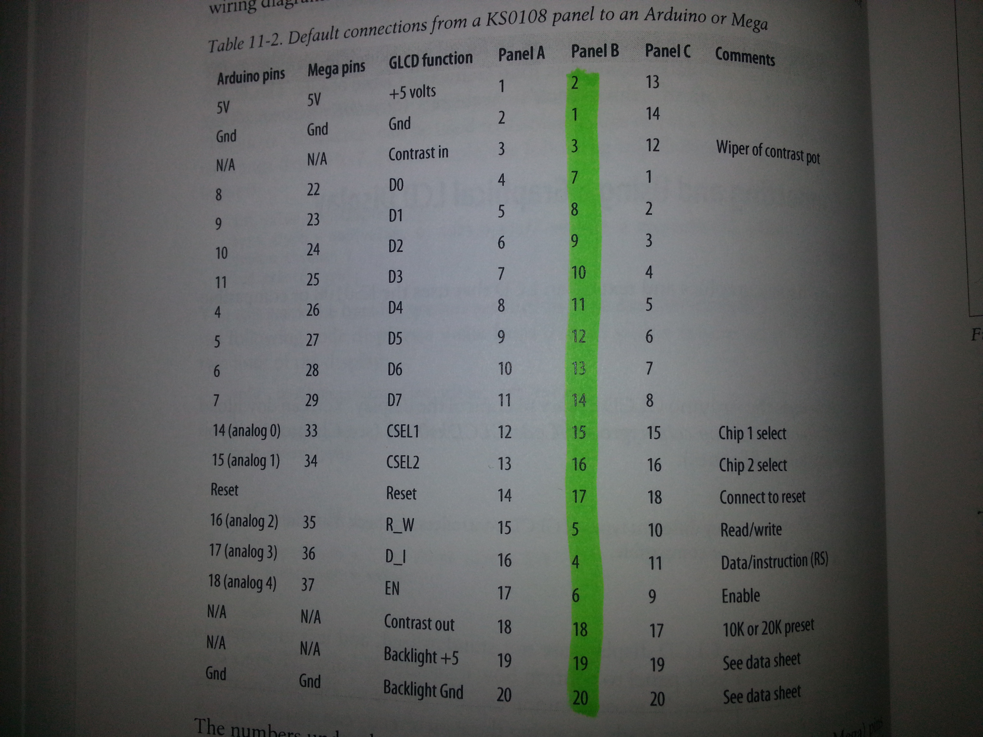
Here is the wiring configuration and the display type I’ve used:
amigo como te va me puedes ayudar con las conexiones de la shield arduino x favor
How to make source code with CVAVR 2.5.3 and use ATMega8535
??
How to make source code ECG use CVAVR 2.5.3???
Do you have a curcuit diagram (proto shield->GLCD to the Arduino)?
Which type of the KS0108 did you use?
Best regards!
I’ve added an image of my wiring configuration. There it also says which module I’ve used.
Thanks a lot! I really appreciate that!
Thanks very much, but how can I modify the dots to normal line on the glcd instead of drawing with dots