Sometimes I feel the need for a spot welder for welding battery tabs. Since soldering batteries can damage their chemistry and commercial spot welders are too expensive, I decided to build my own from scrap. I don’t recommend doing this if you are not confident with electrical stuff since this project ivolves mains voltage and high currents which result in an overall power of around 1000W! You have been warned!

Microwave oven transformers (MOTs) can be obtained for free and have great potential to be used or abused in various projects. One popular use of MOTs is in DIY spot welders. One has to remove the secondary (high voltage) winding and sqeeze in 2-3 turns of heavy gauge copper wire in order to get 1.5-3V @ ca. 400A. There is an infinite amount of information on how to do this online so I won’t cover it too deeply.
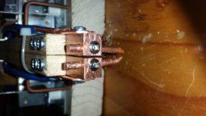
I was able to squeeze 2.5 turns onto the core using ca. 8mm thick stranded copper wire. The electrode blocks are made from pure copper (12x12x50mm copper bars) to minimize resistance and sink the heat. The lugs that connect the wire to the blocks can be made from copper sheets or copper pipe. The welding electrodes are 4.5mm solid copper wire with pointed tips. I had to experiment a little with electrode distance and tip geometry. 3-10mm distance and round tip geometry are probably good starting points.

In order to get consistent welds, some parameters have to be controlled with the most important being mechanical force of the electrode to the workpiece and duration of the high current pulse. The idea behind resistance spot welding is that the spots where electrodes touch the workpiece are the areas of highest electrical resistance and therefore they heat up, melt and fuse together. My welder is built in a “series configuration” which means that both electrodes are at the top as opposed to the alternative variant where one is at the top end the other at the bottom. It is important for both welding electrodes to have near-equal mechanical force on the workpiece and therefore both are spring-loaded individually. Two microswitches in series ensure that the same force on every electrode is applied every time. Only when both microswitches are triggered, the welding pulse is applied. Afterwards the system waits for some seconds until the next weld can be performed. Note that the cable tie on the pictures only holds both arms together losely. They are still able to move away from each other for at least 10mm which is sufficient.


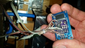
An Attiny85 breakout board takes care of pulse timing. The pulse duration can be adjusted with a 5k potentiometer. A TM1637-based 4 digit 7 segment display shows its duration in milliseconds. A solid state relay for AC voltage turns on the MOT for the set duration. The control circuit is powered by a small 5V 1A AC-DC converter of asian origin. All GPIO pins of the Tiny are finally occupied. The Attiny85 was programmed using the Arduino IDE and while the code is primitive, it does its job well:
//Spot welder controller, simple "blocking code using delays
//uses TM1637 4digit LED display board
//D2: data, D1: clock of TM1637
//D0: solid state relay to switch the MOT
//A3: potentiometer (5k to 50k)
//D4: trigger (2 microswitches in series for each welding electrode)


#include <Arduino.h>
#include <TM1637Display.h>

// Module connection pins (Digital Pins)
#define CLK 1
#define DIO 2
#define SSR 0
#define POT A3
#define TRIG 4

#define maxPulseLength 500

int weldingTimer = 400; //in ms
int pauseTimer = 4000;
int addr=0;
TM1637Display display(CLK, DIO);

void setup() {
  display.setBrightness(7);
  pinMode(TRIG, INPUT_PULLUP);
  pinMode(SSR, OUTPUT);
  digitalWrite(SSR,LOW);
  //value = EEPROM.read(addr);
}

void loop() {
  int anVal = analogRead(POT);
  weldingTimer=map(anVal,0,1024,0,maxPulseLength);
  display.showNumberDec(weldingTimer);

  if(digitalRead(TRIG)==LOW){
    digitalWrite(SSR,HIGH);
    delay(weldingTimer);
    digitalWrite(SSR,LOW);
    delay(pauseTimer);
  }
}
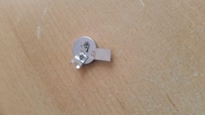
This system has plenty of power. It’s probably even over-powered for battery tab welding so make sure to start with small welding pulses of around 20ms and increase until the weld sticks well. With 70ms and an electrode distance of 3mm I managed to burn a hole through an empty coin cell in an attempt to weld a 0.1mm nickel strip to it. Experiment on scrap metal before you proceed to serious business such as 18650 cells.

