Nowadays anyone can order cheap professionally manufactured PCBs from one’s own designs, as well as Kapton stencils from OSH Park (https://www.oshstencils.com/). This inspired me to take my electronics skills to the next level by building a temperature-controlled reflow oven out of a small toaster oven after I’ve been into 3D printing for quite a while. I’ve been gathering parts slowly for some time and one day a 40A solid state relay (which is overkill for this particular project), a K type thermocouple with MAX6675 amplifier (which has been discontinued to be replaced with the MAX31855) and some standard components have united to form this lovely tool.
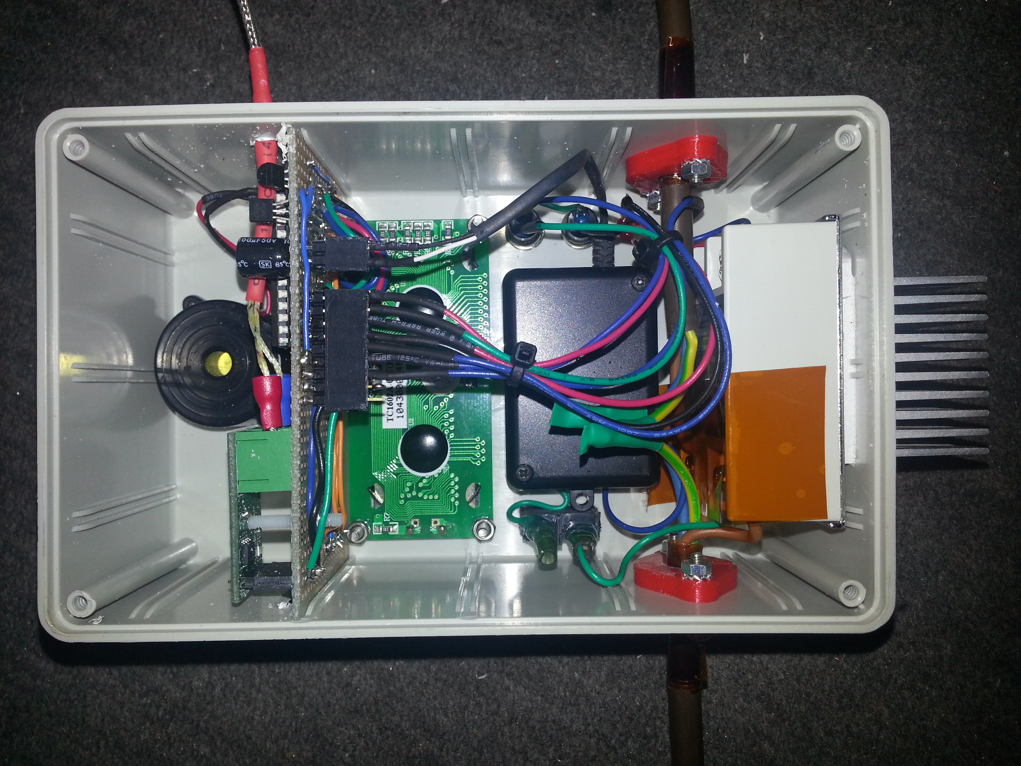
I’ve constructed my oven controller to be compatible with the Reflow Oven Controller Shield project by Rocketscream, since the algorithm is well-tested and versatile. A minimal Arduino configuration on a perfboard was built to fit into the PCB slots of a strapubox enclosure. A standard 16×2 LCD and a button form the user interface. The SSR has got a heatsink but doesn’t even get warm with the small oven which draws <2 Amps. The electronics is powered by a samsung phone charger which has been fitted into the small black enclosure for perfect insulation. It's a small switching power supply capable of delivering 5V @ 750mA. The red parts on the input/output power cable are self-designed and 3D printed strain reliefs for the thick cable
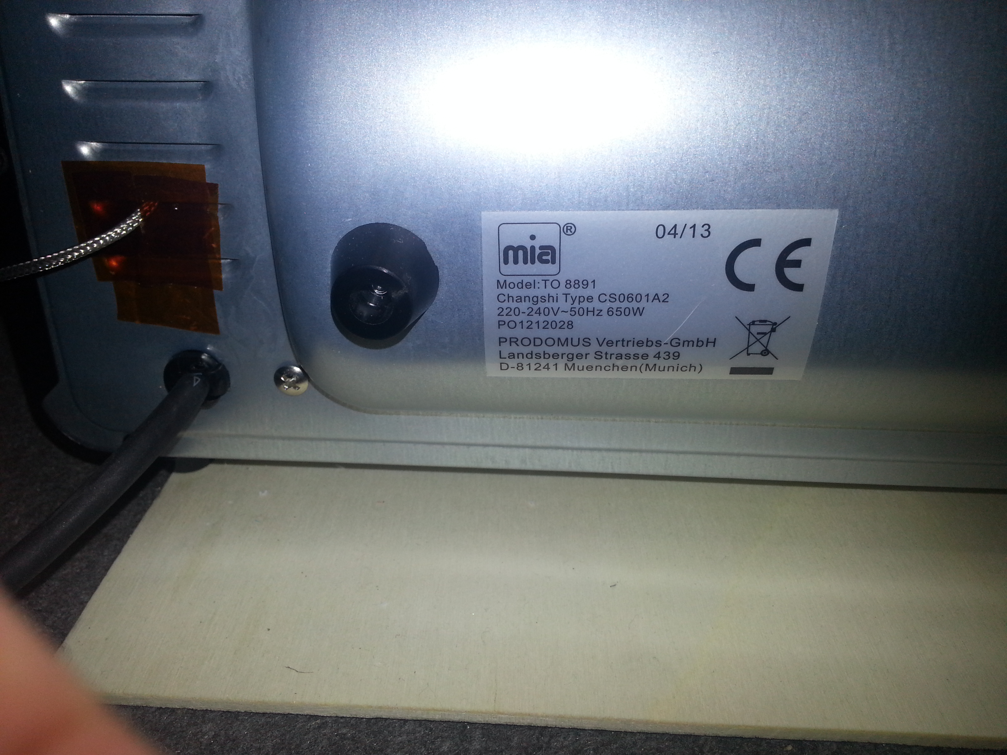
The oven is the smallest and cheapest toaster oven I could find. It has got a top and a bottom 350W heating element (the ceramic white ones that are supposed to be better for reflow purposes) and cost about 19€ in Berlet.
The heating elements are covered with slotted sheet metal, which should avoid direct exposure of the foods/PCBs to the infrared/heat radiation I suppose. I’ve removed all the “guts” from the original oven and wired the two elements in parallel. The mains cable has been left in place. A hole for the thermocouple has been drilled on the side of the inside wall.
First dry-run tests with the included baking tray resulted in the following temperature profile:
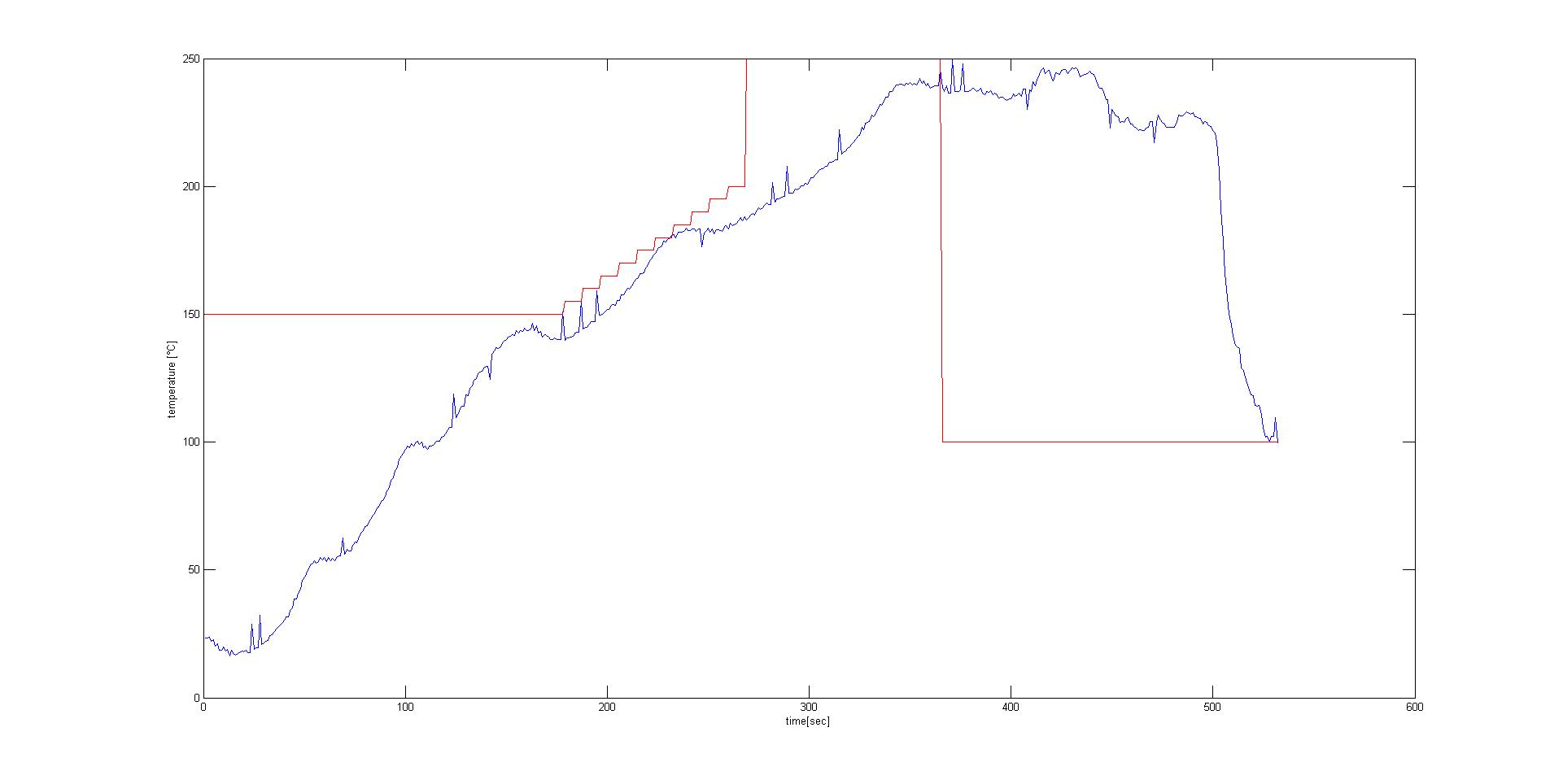
The software transmits the temperature value measured by the thermocouple via serial, which it does every second. I simply inserted a bluetooth module into the FTDI header, saved the values in a terminal program on a paired PC and plotted them with MATLAB. Attempts without baking tray resulted in quicker responses in measured temperature due to the lower thermal mass.
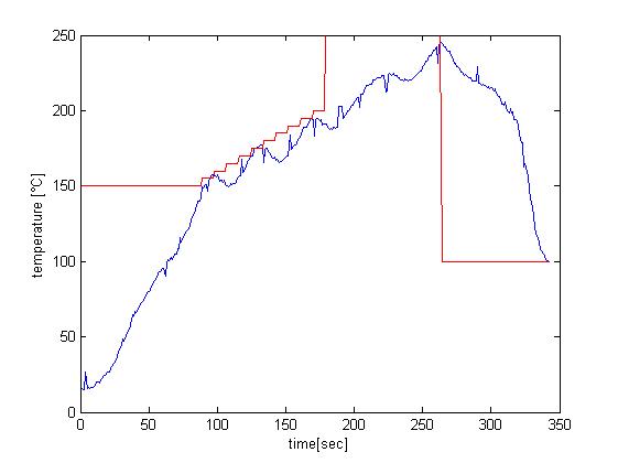
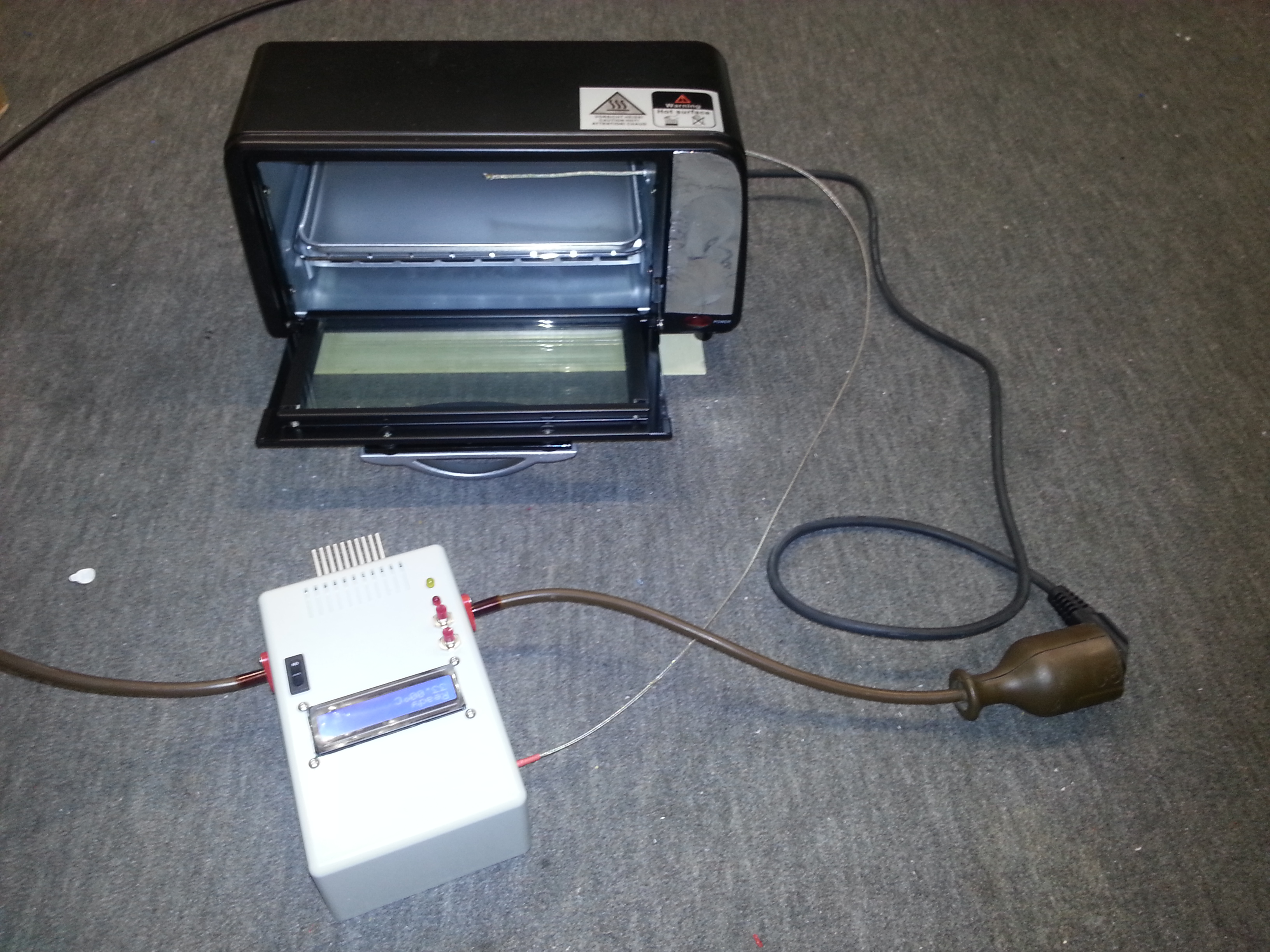
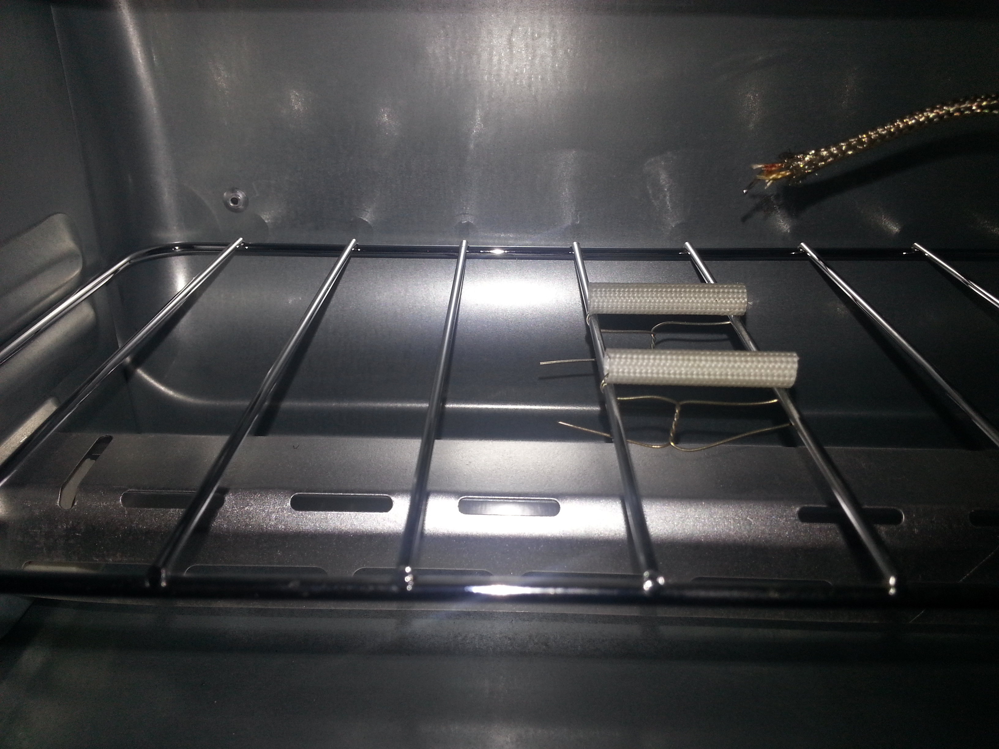
I decided to solder my boards without tray to have more control over the temperature on the board, since the oven doesn’t have a convection fan. To have as little thermal mass under the board as possible I installed two heat-resistant insulation sleeves. The end of the thermocouple can be lowered to touch the PCB directly by moving its wire outsie of the oven. This gives you better measurements of the temperature that the parts and the board surface are exposed to. I removed the metal shell on the end of the thermocouple to further reduce its thermal mass.
This is the setup that works best so far. The project is a full success. I’m very pleased with the rocketscream algorithm, my controller and the tiny oven. First results with lead-free solderpaste were close to perfect.