Recently I’ve come across this high quality device while looking for a permanent magnet alternator to experiment with.
It’s supposed to be a generator designed particularly for wind turbines and able to deliver 500W. Not bad. Its weight is about 3.5kg. The shaft diameter is 20mm. That’s about all info I could get from the seller.
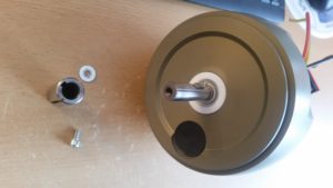
The inner shaft diameter is 12mm, the 20mm slotted steel adapter can be taken off. It is sealed off with a plastic “bearing” with a steel spring around it (not visible in the picture). Could be polyethylene or similar to protect it from the elements. The chassis is supposedly cast aluminium at the front and a precision machined Al cover at the back with a chunky rubber ring between back cover and alternator. The alternator itself is a 90mm diameter high quality brushless outrunner motor/alternator by CPM with the entire stator potted in some kind of plastic. The rotor was made from machined steel. After visiting the webpage on the label you get forwarded to http://www.cpmotion.com/ A quick search for the part number was not successful.
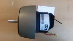
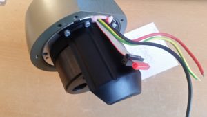
The injection molded black plastic cover prevents the cables to touch the rotor of the alternator. Nice attention to detail. The black connector on the ribbon cable I have attached myself because I had a 20pin one lying around and 0.1 inch headers are much easier to work with.
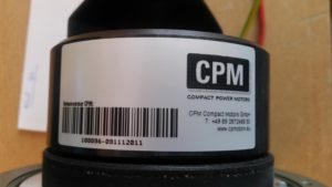
I got the thing from ebay (new and unused!) for less than 50€ and expected a 3phase device because of the three wires coming out of it. Instead it turned out to have a DC output (the yellow and green one is just tied to the chassis). After cranking it up by hand for testing I figured out that some charge was stored across the red and black wire which implied that there’s a capacitor hidden somewhere and that it had to be DC. The fact alone that the manufacturer had chosen red and black should actually be enough of a clue that it’s a DC device. Besides the power cables a 20pin connector with a ribbon cable is poking out of the enclosure as well. Asking the seller for datasheets was not successful. I was only told that it is worth much more than what I payed for it and that it’s from a company that went bankrupt. Visiting the website on the label did not give me a datasheet for this particular device either. The only thing I was able to find out is that the manufacturer (CPM) uses the CAN bus on their other products to control their devices (CAN 2.0A) besides some digital and analog pins on their control interfaces. At least something if we assume that not only the alternator but also the control electronics was designed by them.
So the only thing left is trying to reverse engineer it. After spinning the generator up with a drill you notice a very short pulse of mechanical resistance after a couple of turns. I thought maybe there is some kind of initialization routine happening after power-up. Attaching a 60W H4 automotive light bulb as a load showed that the device is definitely useful to generate DC electricity. The bulb could be brought to full brightness easily. A voltage measurement on different rpm without a load revealed that the voltage can easily go up to 48V.
After removing all screws I tried to open the front part but I couldn’t do it for some reason and therefore I decided to not do potentially irreversible stuff for now.
Instead the next reasonable step would be to crank the alternator up evenly with a drill and measure voltages on some pins. All we know to this point is that it’s likely to find a CAN interface on the header, which means that 2 pins should measure about 2.5V (depending on whether it’s 3.3V or 5V CAN) against some ground reference.
In the picture below you see the results of mapping out the interface.
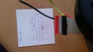
Indeed I was able to find -2.5V on the pins irrespective of RPM. Then I reversed polarity of my oscilloscope/multimeter and took the GND pin as a reference for further measurements. In total I was only able to find 2 pins with 2.5V which is another progress. 2 other pins had about 3.3V on them and 3 Pins had variable voltage (0-2V in my tests) depending on the RPM.
My ambition with this device is to try to communicate with it via CAN and try to repurpose its control electronics, as it seems to be well-engineered apparatus all in all. The fact that it has a pulse of resistance at startup makes it possible for this thing to have an internal, probably configurable load inside which might be used as a brake. Also I’m curious to know what kind of data it is capable to spit out. If I were the engineer, I’d probably have it measure power and RPM…let’s see. My approach will be to try to connect an Arduino via MCP2515 to the CAN pins and see whether I get any response.

Hi, did you find this chart http://www.cpmotion.com/img/power-packs-schema-L.jpg ?
There is a software called “Motion Workbench” for extensive monitoring (e.g. motor temperature, pcb temperature, etc.) and safety switch off
Interface: CAN
RS485
Analog
Best, Matt
Hey, thanks for the info. I’ve had a look at all datasheets I could possibly get hold of and the image looks familiar.
CPMotion has sent me 2 datasheets of their more recent generators but they are different models. They said that according to the serial number this one was developed/manufactured in 2012 but they haven’t found a datasheet specifically for this model yet.
I’ll try Motion Workbench soon.
Greetings, AJ
I ordered one too! Maybe we can exchange information soon.
Matt
Nice. I would love to hear about your progress. Tell me if you were able to take the thing apart. I still wasn’t able to….