Especially when you are dealing with 0603 and smaller components and solder paste, even fine tweezers can become annoying because of their magnetic properties. I’ve looked at professional suction pick and place tools and noticed that the main parts they consist of can be found in my medical parts tray. A friend has kindly donated me a tiny “single-use” 3V vacuum pump which is used in wound treatment and I’ve decided to use this thing in this project. Fortunately you can buy them on ebay.
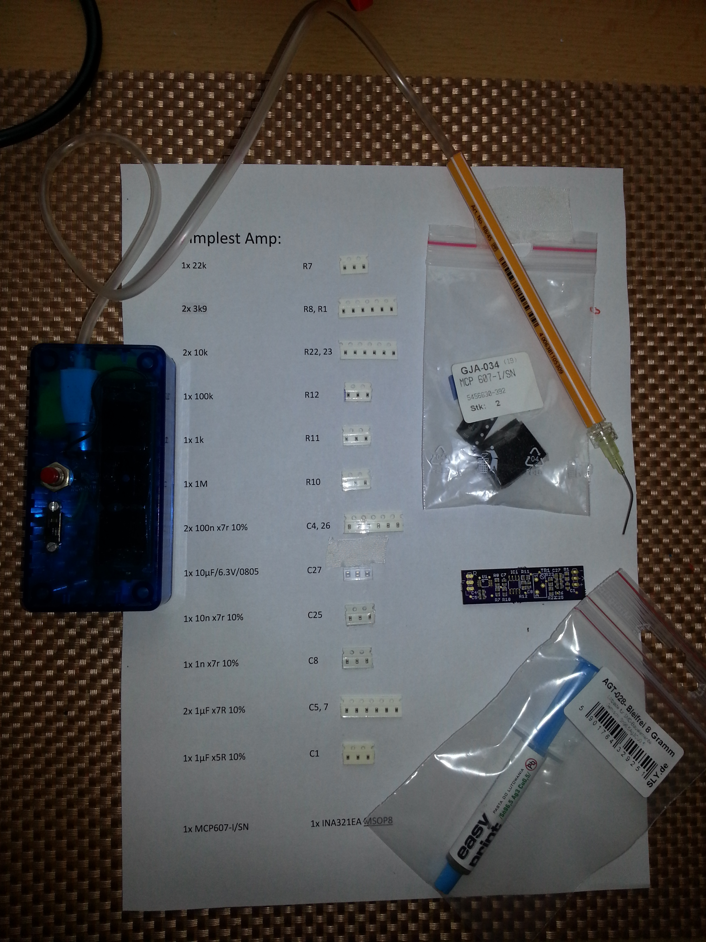
Other parts you’ll need is a drip infusion set, a pen or small 6mm pipe and syringe needles with a diameter of your choice. The green and yellow ones work fine for 0603 and smaller. Also you’ll need 2 AA batteries or one 18650 cell with the appropriate holder and a momentary switch to power the pump. The assembly is fairly easy.
The needles are shortened with a dremel, bent to shape and filed flat at the tip with a fine diamond file. You can easily change tips for different component sizes. The device is meant for double-handed operation, since you could be too inprecise on your pick and place hand if you had a switch directly on the pen. So you have the enclosure in the other hand and the pick and place madness can begin. Because the tip is far from air tight the part falls off immediately after you release the trigger. Oftentimes the adhesion to the solder paste on the PCB is even stronger than the suction.
I like attaching the component belts to the bill of materials that I’ve printed out so everything is in perfect order and every step of the process is clear and quick. Errors can be avoided that way.
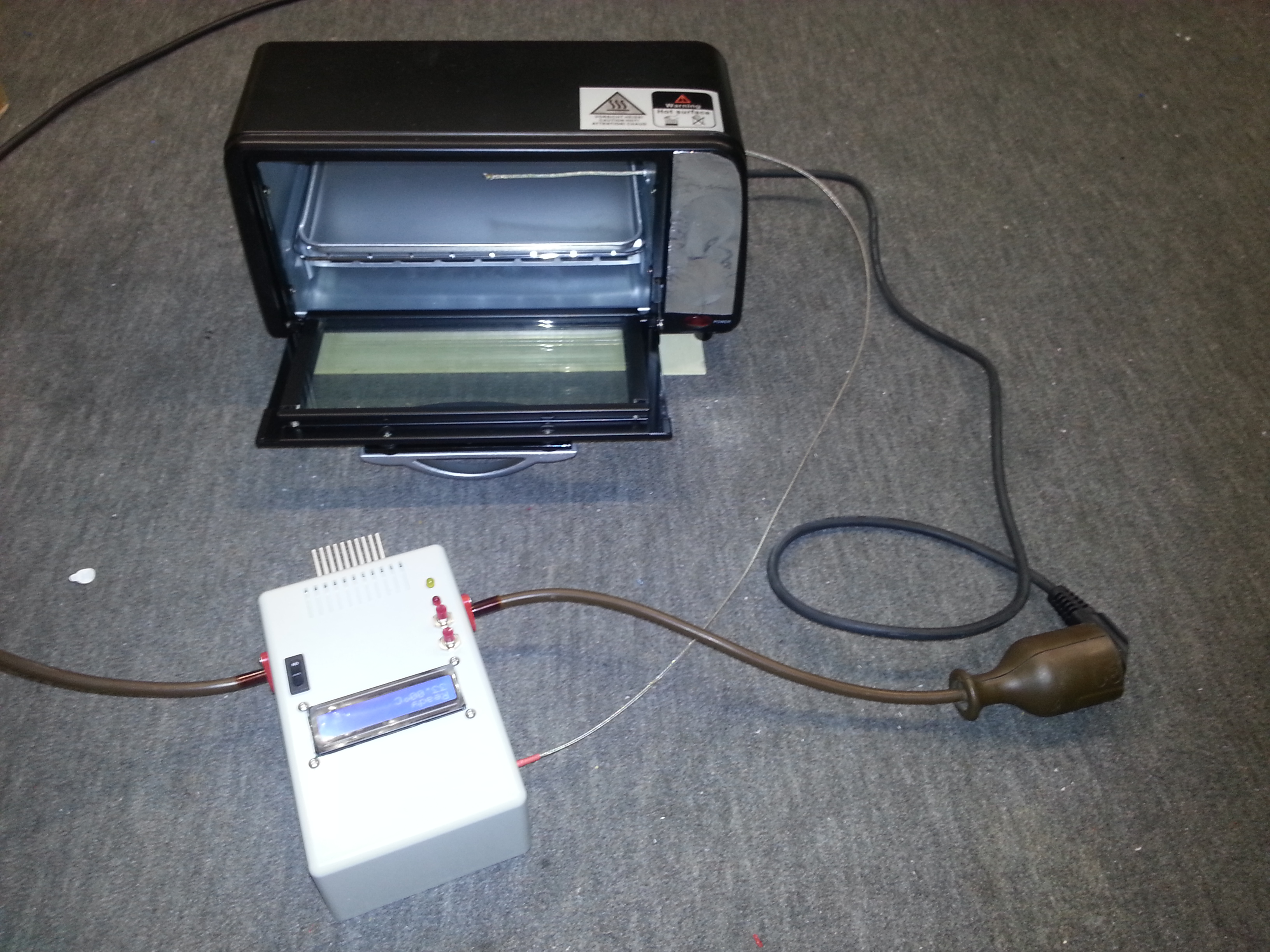
Nowadays anyone can order cheap professionally manufactured PCBs from one’s own designs, as well as Kapton stencils from OSH Park (https://www.oshstencils.com/). This inspired me to take my electronics skills to the next level by building a temperature-controlled reflow oven out of a small toaster oven after I’ve been into 3D printing for quite a while. I’ve been gathering parts slowly for some time and one day a 40A solid state relay (which is overkill for this particular project), a K type thermocouple with MAX6675 amplifier (which has been discontinued to be replaced with the MAX31855) and some standard components have united to form this lovely tool.
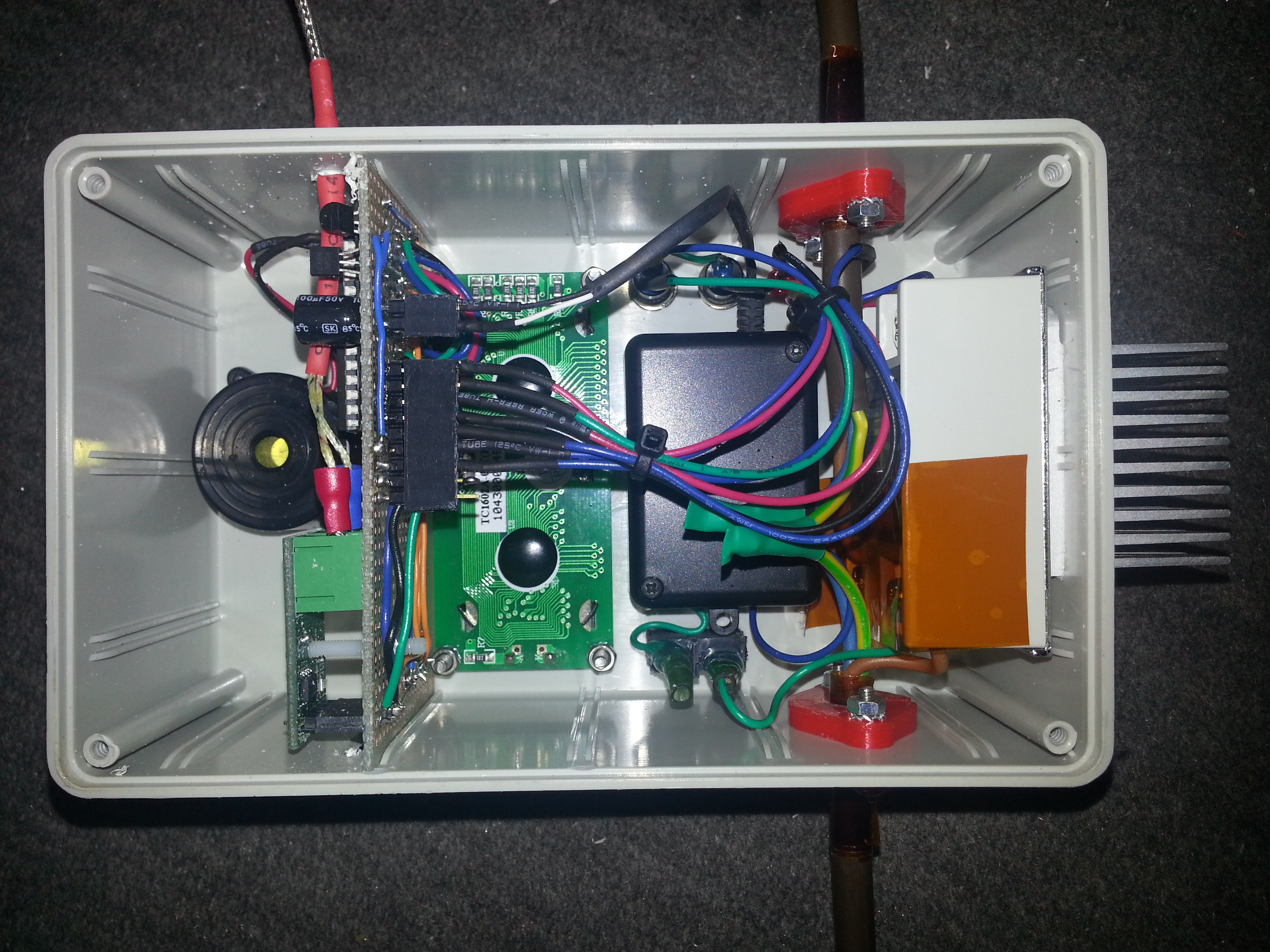
I’ve constructed my oven controller to be compatible with the Reflow Oven Controller Shield project by Rocketscream, since the algorithm is well-tested and versatile. A minimal Arduino configuration on a perfboard was built to fit into the PCB slots of a strapubox enclosure. A standard 16×2 LCD and a button form the user interface. The SSR has got a heatsink but doesn’t even get warm with the small oven which draws <2 Amps. The electronics is powered by a samsung phone charger which has been fitted into the small black enclosure for perfect insulation. It's a small switching power supply capable of delivering 5V @ 750mA. The red parts on the input/output power cable are self-designed and 3D printed strain reliefs for the thick cable
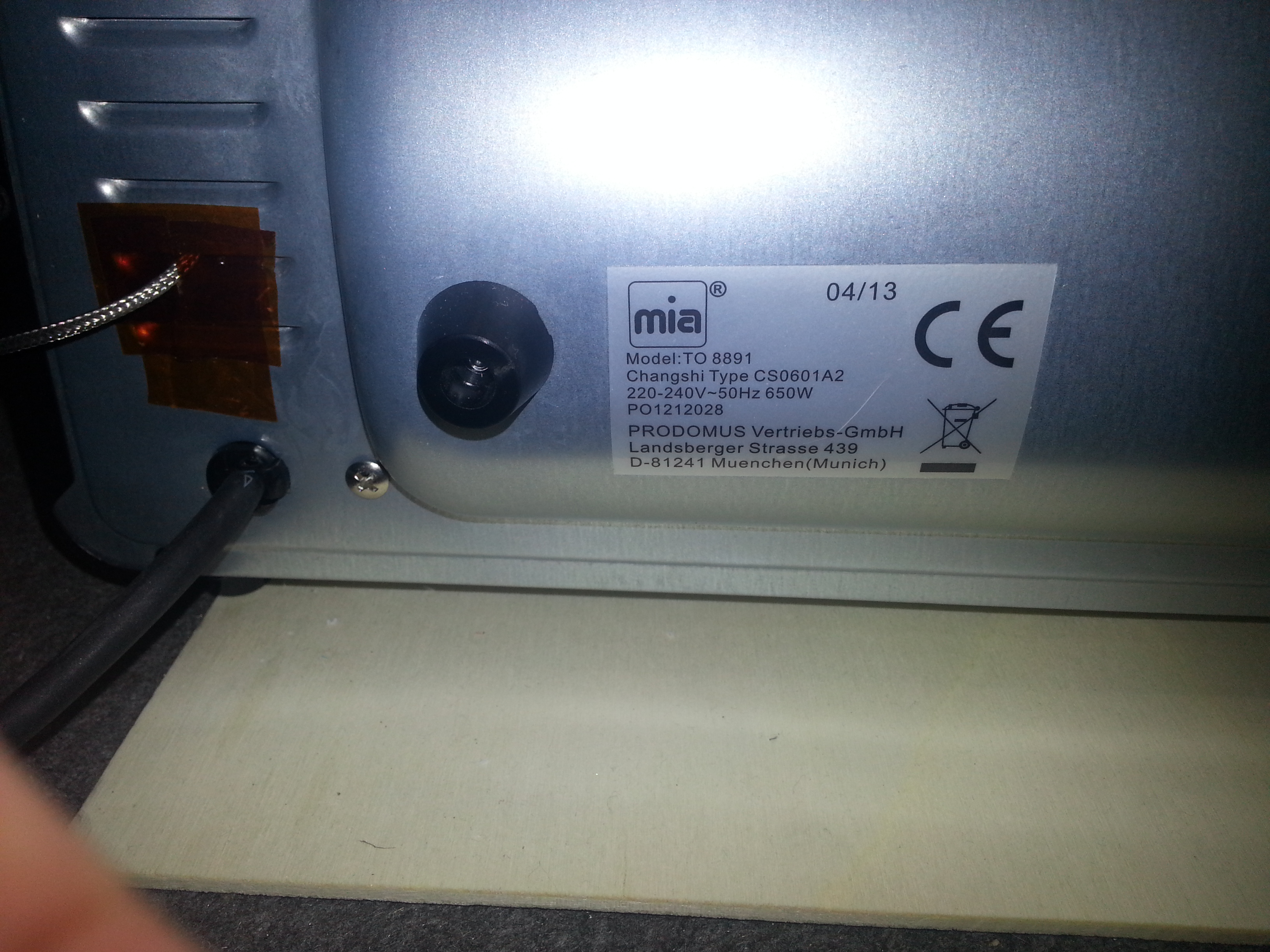
The oven is the smallest and cheapest toaster oven I could find. It has got a top and a bottom 350W heating element (the ceramic white ones that are supposed to be better for reflow purposes) and cost about 19€ in Berlet.
The heating elements are covered with slotted sheet metal, which should avoid direct exposure of the foods/PCBs to the infrared/heat radiation I suppose. I’ve removed all the “guts” from the original oven and wired the two elements in parallel. The mains cable has been left in place. A hole for the thermocouple has been drilled on the side of the inside wall.
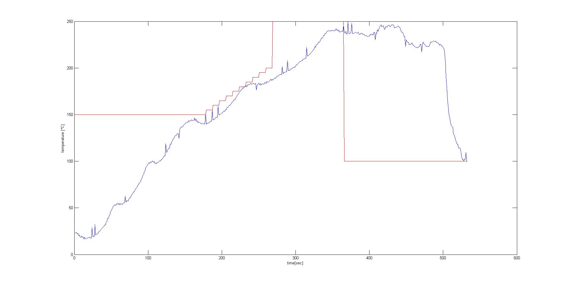
First dry-run tests with the included baking tray resulted in the following temperature profile:
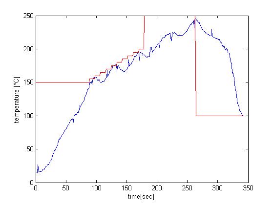
The software transmits the temperature value measured by the thermocouple via serial, which it does every second. I simply inserted a bluetooth module into the FTDI header, saved the values in a terminal program on a paired PC and plotted them with MATLAB. Attempts without baking tray resulted in quicker responses in measured temperature due to the lower thermal mass.
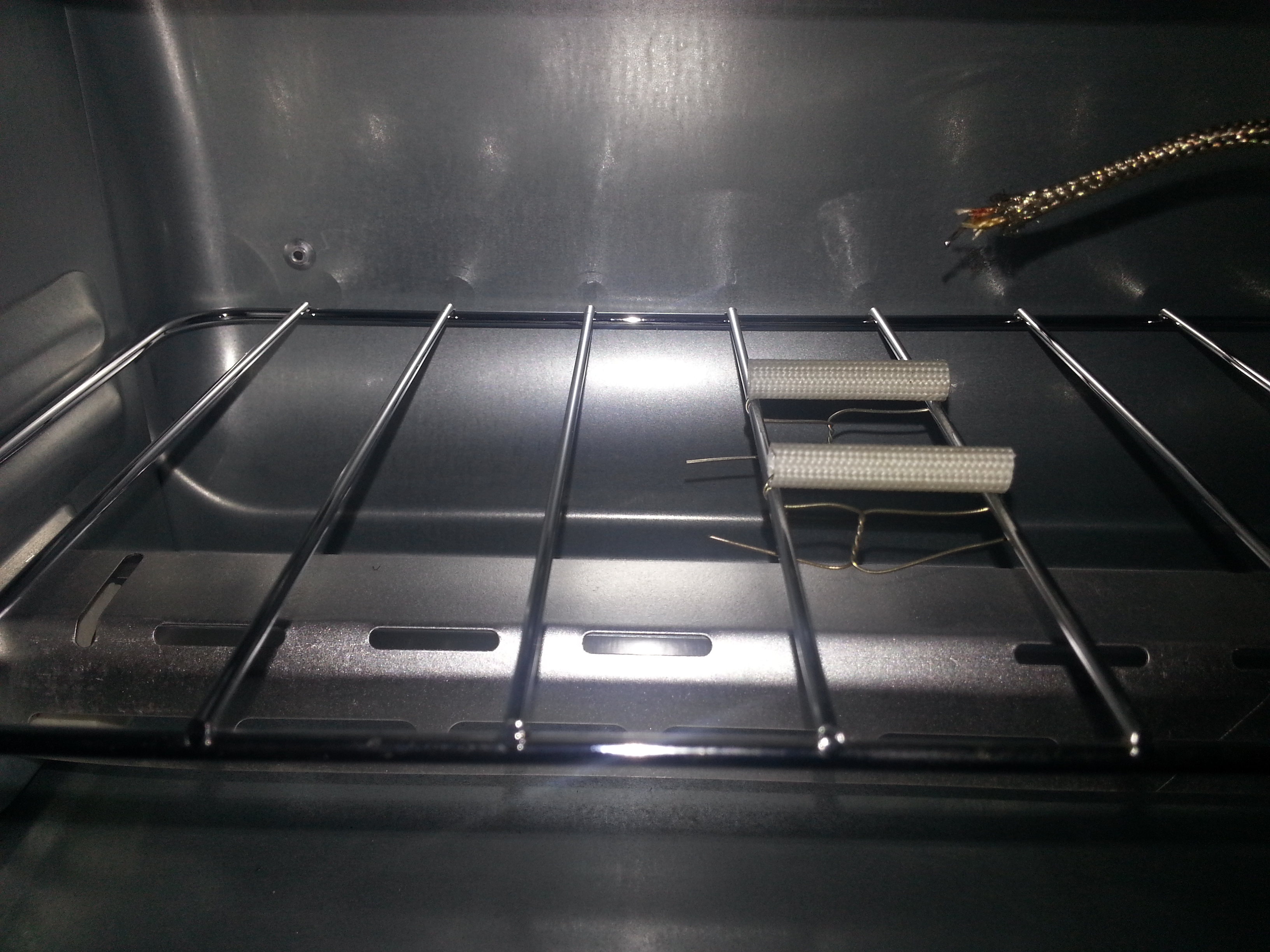
I decided to solder my boards without tray to have more control over the temperature on the board, since the oven doesn’t have a convection fan. To have as little thermal mass under the board as possible I installed two heat-resistant insulation sleeves. The end of the thermocouple can be lowered to touch the PCB directly by moving its wire outsie of the oven. This gives you better measurements of the temperature that the parts and the board surface are exposed to. I removed the metal shell on the end of the thermocouple to further reduce its thermal mass.
This is the setup that works best so far. The project is a full success. I’m very pleased with the rocketscream algorithm, my controller and the tiny oven. First results with lead-free solderpaste were close to perfect.
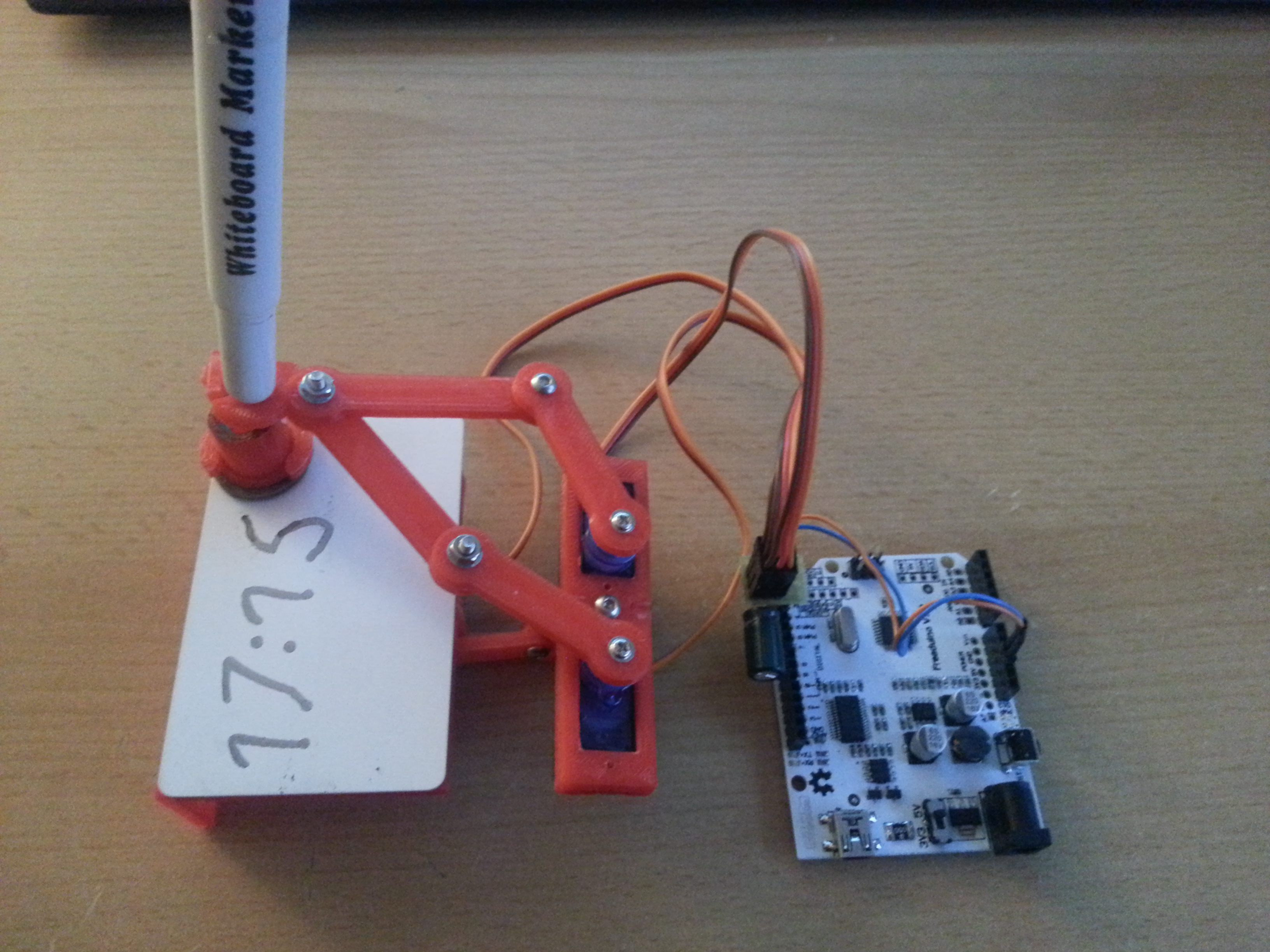
I’ve printed the parts for a Plot Clock in PLA and assembled it in a pretty much standard configuration, which worked great. Quite a bit of filing and sanding was necessary, but it was worth it, the final device was quite easy to calibrate. The only thing I found was missing is time keeping capability, so I added a DS1307 I2C real time clock module, which is a straightforward procedure. Learn how to set up the RTC HERE.
Before you run the sketch that sets the time on the RTC, make sure to remove the battery once to reset the DS1307. Put the battery back in and run the sketch. My modification on the Plot Clock code simply fetches the time once every time you power the arduino up. Further timekeeping is done by the ATmega.
// Plotclock
// cc - by Johannes Heberlein 2014
// v 1.01
// thingiverse.com/joo   wiki.fablab-nuernberg.de

// units: mm; microseconds; radians
// origin: bottom left of drawing surface

// time library see http://playground.arduino.cc/Code/time

// Date and time functions using a DS1307 RTC connected via I2C and Wire lib

    #include <Wire.h>
    #include "RTClib.h"

    RTC_DS1307 RTC;

// delete or mark the next line as comment when done with calibration
//#define CALIBRATION

// When in calibration mode, adjust the following factor until the servos move exactly 90 degrees
#define SERVOFAKTOR 555

// Zero-position of left and right servo
// When in calibration mode, adjust the NULL-values so that the servo arms are at all times parallel
// either to the X or Y axis
#define SERVOLEFTNULL 2075
#define SERVORIGHTNULL 1065

#define SERVOPINLIFT  2
#define SERVOPINLEFT  3
#define SERVOPINRIGHT 4

// lift positions of lifting servo
#define LIFT0 1350 // on drawing surface
#define LIFT1 1180// between numbers
#define LIFT2 850  // going towards sweeper

// speed of liftimg arm, higher is slower
#define LIFTSPEED 1500

// length of arms
#define L1 35
#define L2 55.1
#define L3 13.2


// origin points of left and right servo
#define O1X 22
#define O1Y -25
#define O2X 47
#define O2Y -25


#include <Time.h> // see http://playground.arduino.cc/Code/time
#include <Servo.h>

int servoLift = 1500;

Servo servo1;  //
Servo servo2;  //
Servo servo3;  //

volatile double lastX = 75;
volatile double lastY = 47.5;

int last_min = 0;

void setup()
{

  Wire.begin();
  RTC.begin();
  DateTime now = RTC.now();
  // Set current time only the first to values, hh,mm are needed
  int rhour = now.hour();
  int rminute = now.minute();
  setTime(rhour,rminute,0,0,0,0);

  drawTo(75.2, 47);
  lift(0);
  servo1.attach(SERVOPINLIFT);  //  lifting servo
  servo2.attach(SERVOPINLEFT);  //  left servo
  servo3.attach(SERVOPINRIGHT);  //  right servo

  delay(1000);


}

void loop()
{

#ifdef CALIBRATION

  // Servohorns will have 90° between movements, parallel to x and y axis
  drawTo(-3, 29.2);
  delay(500);
  drawTo(74.1, 28);
  delay(500);

#else
  //DateTime now = RTC.now();

  int i = 0;
  if (last_min != minute()) {

    if (!servo1.attached()) servo1.attach(SERVOPINLIFT);
    if (!servo2.attached()) servo2.attach(SERVOPINLEFT);
    if (!servo3.attached()) servo3.attach(SERVOPINRIGHT);

    lift(0);

    hour();


    while ((i+1)*10 <= hour())
    {
      i++;
    }

    number(3, 3, 111, 1);
    number(5, 25, i, 0.9);
    number(19, 25, (hour()-i*10), 0.9);
    number(28, 25, 11, 0.9);

    i=0;
    while ((i+1)*10 <= minute())
    {
      i++;
    }
    number(34, 25, i, 0.9);
    number(48, 25, (minute()-i*10), 0.9);
    lift(2);
    drawTo(74.2, 47.5);
    lift(1);
    last_min = minute();

    servo1.detach();
    servo2.detach();
    servo3.detach();
  }

#endif

}

// Writing numeral with bx by being the bottom left originpoint. Scale 1 equals a 20 mm high font.
// The structure follows this principle: move to first startpoint of the numeral, lift down, draw numeral, lift up
void number(float bx, float by, int num, float scale) {

  switch (num) {

  case 0:
    drawTo(bx + 12 * scale, by + 6 * scale);
    lift(0);
    bogenGZS(bx + 7 * scale, by + 10 * scale, 10 * scale, -0.8, 6.7, 0.5);
    lift(1);
    break;
  case 1:

    drawTo(bx + 3 * scale, by + 15 * scale);
    lift(0);
    drawTo(bx + 10 * scale, by + 20 * scale);
    drawTo(bx + 10 * scale, by + 0 * scale);
    lift(1);
    break;
  case 2:
    drawTo(bx + 2 * scale, by + 12 * scale);
    lift(0);
    bogenUZS(bx + 8 * scale, by + 14 * scale, 6 * scale, 3, -0.8, 1);
    drawTo(bx + 1 * scale, by + 0 * scale);
    drawTo(bx + 12 * scale, by + 0 * scale);
    lift(1);
    break;
  case 3:
    drawTo(bx + 2 * scale, by + 17 * scale);
    lift(0);
    bogenUZS(bx + 5 * scale, by + 15 * scale, 5 * scale, 3, -2, 1);
    bogenUZS(bx + 5 * scale, by + 5 * scale, 5 * scale, 1.57, -3, 1);
    lift(1);
    break;
  case 4:
    drawTo(bx + 10 * scale, by + 0 * scale);
    lift(0);
    drawTo(bx + 10 * scale, by + 20 * scale);
    drawTo(bx + 2 * scale, by + 6 * scale);
    drawTo(bx + 12 * scale, by + 6 * scale);
    lift(1);
    break;
  case 5:
    drawTo(bx + 2 * scale, by + 5 * scale);
    lift(0);
    bogenGZS(bx + 5 * scale, by + 6 * scale, 6 * scale, -2.5, 2, 1);
    drawTo(bx + 5 * scale, by + 20 * scale);
    drawTo(bx + 12 * scale, by + 20 * scale);
    lift(1);
    break;
  case 6:
    drawTo(bx + 2 * scale, by + 10 * scale);
    lift(0);
    bogenUZS(bx + 7 * scale, by + 6 * scale, 6 * scale, 2, -4.4, 1);
    drawTo(bx + 11 * scale, by + 20 * scale);
    lift(1);
    break;
  case 7:
    drawTo(bx + 2 * scale, by + 20 * scale);
    lift(0);
    drawTo(bx + 12 * scale, by + 20 * scale);
    drawTo(bx + 2 * scale, by + 0);
    lift(1);
    break;
  case 8:
    drawTo(bx + 5 * scale, by + 10 * scale);
    lift(0);
    bogenUZS(bx + 5 * scale, by + 15 * scale, 5 * scale, 4.7, -1.6, 1);
    bogenGZS(bx + 5 * scale, by + 5 * scale, 5 * scale, -4.7, 2, 1);
    lift(1);
    break;

  case 9:
    drawTo(bx + 9 * scale, by + 11 * scale);
    lift(0);
    bogenUZS(bx + 7 * scale, by + 15 * scale, 5 * scale, 4, -0.5, 1);
    drawTo(bx + 5 * scale, by + 0);
    lift(1);
    break;

  case 111:

    lift(0);
    drawTo(70, 46);
    drawTo(65, 43);

    drawTo(65, 49);
    drawTo(5, 49);
    drawTo(5, 45);
    drawTo(65, 45);
    drawTo(65, 40);

    drawTo(5, 40);
    drawTo(5, 35);
    drawTo(65, 35);
    drawTo(65, 30);

    drawTo(5, 30);
    drawTo(5, 25);
    drawTo(65, 25);
    drawTo(65, 20);

    drawTo(5, 20);
    drawTo(60, 44);

    drawTo(75.2, 47);
    lift(2);

    break;

  case 11:
    drawTo(bx + 5 * scale, by + 15 * scale);
    lift(0);
    bogenGZS(bx + 5 * scale, by + 15 * scale, 0.1 * scale, 1, -1, 1);
    lift(1);
    drawTo(bx + 5 * scale, by + 5 * scale);
    lift(0);
    bogenGZS(bx + 5 * scale, by + 5 * scale, 0.1 * scale, 1, -1, 1);
    lift(1);
    break;

  }
}


void lift(char lift) {
  switch (lift) {
    // room to optimize  !

  case 0: //850

      if (servoLift >= LIFT0) {
      while (servoLift >= LIFT0)
      {
        servoLift--;
        servo1.writeMicroseconds(servoLift);
        delayMicroseconds(LIFTSPEED);
      }
    }
    else {
      while (servoLift <= LIFT0) {
        servoLift++;
        servo1.writeMicroseconds(servoLift);
        delayMicroseconds(LIFTSPEED);

      }

    }

    break;

  case 1: //150

    if (servoLift >= LIFT1) {
      while (servoLift >= LIFT1) {
        servoLift--;
        servo1.writeMicroseconds(servoLift);
        delayMicroseconds(LIFTSPEED);

      }
    }
    else {
      while (servoLift <= LIFT1) {
        servoLift++;
        servo1.writeMicroseconds(servoLift);
        delayMicroseconds(LIFTSPEED);
      }

    }

    break;

  case 2:

    if (servoLift >= LIFT2) {
      while (servoLift >= LIFT2) {
        servoLift--;
        servo1.writeMicroseconds(servoLift);
        delayMicroseconds(LIFTSPEED);
      }
    }
    else {
      while (servoLift <= LIFT2) {
        servoLift++;
        servo1.writeMicroseconds(servoLift);
        delayMicroseconds(LIFTSPEED);
      }
    }
    break;
  }
}


void bogenUZS(float bx, float by, float radius, int start, int ende, float sqee) {
  float inkr = -0.05;
  float count = 0;

  do {
    drawTo(sqee * radius * cos(start + count) + bx,
    radius * sin(start + count) + by);
    count += inkr;
  }
  while ((start + count) > ende);

}

void bogenGZS(float bx, float by, float radius, int start, int ende, float sqee) {
  float inkr = 0.05;
  float count = 0;

  do {
    drawTo(sqee * radius * cos(start + count) + bx,
    radius * sin(start + count) + by);
    count += inkr;
  }
  while ((start + count) <= ende);
}


void drawTo(double pX, double pY) {
  double dx, dy, c;
  int i;

  // dx dy of new point
  dx = pX - lastX;
  dy = pY - lastY;
  //path lenght in mm, times 4 equals 4 steps per mm
  c = floor(4 * sqrt(dx * dx + dy * dy));

  if (c < 1) c = 1;

  for (i = 0; i <= c; i++) {
    // draw line point by point
    set_XY(lastX + (i * dx / c), lastY + (i * dy / c));

  }

  lastX = pX;
  lastY = pY;
}

double return_angle(double a, double b, double c) {
  // cosine rule for angle between c and a
  return acos((a * a + c * c - b * b) / (2 * a * c));
}

void set_XY(double Tx, double Ty)
{
  delay(1);
  double dx, dy, c, a1, a2, Hx, Hy;

  // calculate triangle between pen, servoLeft and arm joint
  // cartesian dx/dy
  dx = Tx - O1X;
  dy = Ty - O1Y;

  // polar lemgth (c) and angle (a1)
  c = sqrt(dx * dx + dy * dy); //
  a1 = atan2(dy, dx); //
  a2 = return_angle(L1, L2, c);

  servo2.writeMicroseconds(floor(((a2 + a1 - M_PI) * SERVOFAKTOR) + SERVOLEFTNULL));

  // calculate joinr arm point for triangle of the right servo arm
  a2 = return_angle(L2, L1, c);
  Hx = Tx + L3 * cos((a1 - a2 + 0.621) + M_PI); //36,5°
  Hy = Ty + L3 * sin((a1 - a2 + 0.621) + M_PI);

  // calculate triangle between pen joint, servoRight and arm joint
  dx = Hx - O2X;
  dy = Hy - O2Y;

  c = sqrt(dx * dx + dy * dy);
  a1 = atan2(dy, dx);
  a2 = return_angle(L1, (L2 - L3), c);

  servo3.writeMicroseconds(floor(((a1 - a2) * SERVOFAKTOR) + SERVORIGHTNULL));

}