I’ve been doing some projects with the RFD22301, also known as RFduino and therefore decided to make a breakout for it. It’s also the radio used on the OpenBCI v3 system for data transfer, communication and programming. This breakout board can also be used as an OpenBCI dongle and can be plugged directly on this CP2102-based USB to TTL UART converter. Of course any other converter will do as long as it has 3.3V logic level. Watch out for that!
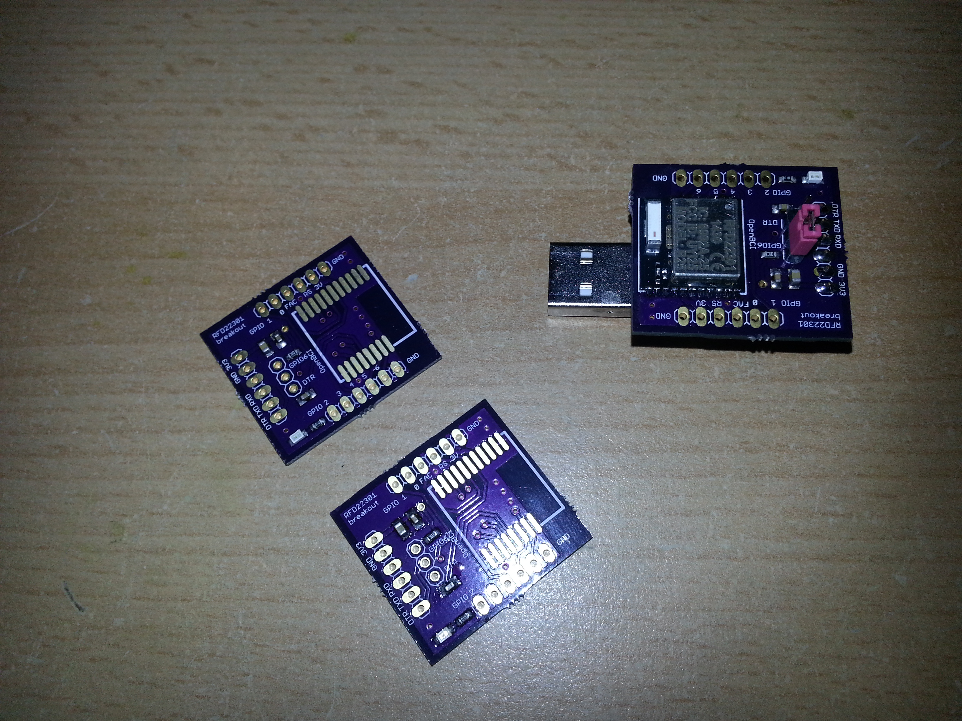
The jumper sets the DTR pin of the USB to serial converter to either the reset of the RFduino or its GPIO6. If it’s on “reset”, the RFduino itself is programmed during code upload. On the other position it starts programming the microcontroller on the OpenBCI board, assuming the OpenBCI firmware is flashed on the RFduinos of both the “Host” and the “Device” side.
Eagle files:
RFduinoBreakout
Hey Kauz how do we program the two RFduino modules for communication? One that we want to use as a dongle and the one on the Open BCI board.
You mentioned in your other post that you are using a wireless protocol (not exactly Bluetooth). Can you please explain the implementation a bit?
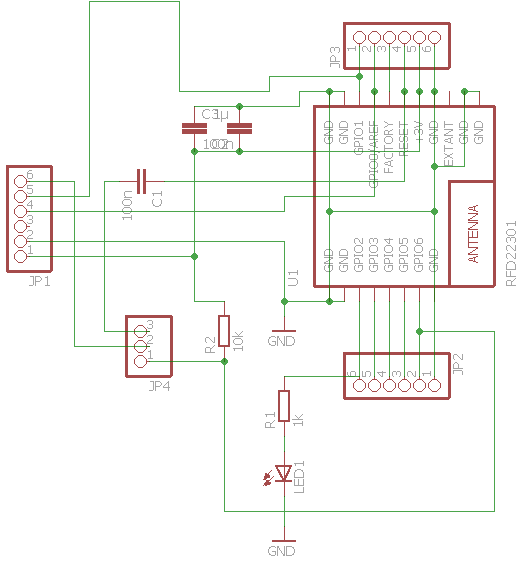
Hi, the dongle RFduino is programmed by setting the jumper on this breakout to “DTR” and uploading the “Radio Host” firmware. The RFduino on the V3 board is programmed by temporarily soldering wires to the four pads on the bottom side of the board which are GND, RFRST, RFRX, RFTX (in the case of the 32bit board). The RFRST connects via a 100nf capacitor to the DTR of the USB-serial converter and the other 3 should be self-explanatory. Here you have to upload the “Radio Device” firmware. For reference, check out the OpenBCI documentation. It’s quite informative: http://docs.openbci.com/Hardware/06-Cyton_Radios_Programming_Tutorial#cyton-radios-programming-tutorial-uploading-device-firmware-to-cyton-board-upload-pass-thru-radio-firmware-version-2xx-fall-2016
Now if you want to program the onboard MCU, we have to set the jumper back to “GPIO6” on the RFduino breakout. don’t forget that (I sometimes do!)
The onboard MCU is then programmed over the air as described here http://docs.openbci.com/Hardware/05-Cyton_Board_Programming_Tutorial
The implementation of the wireless protocol is described in the OpenBCI Github repositories and the source code……