Category Archives: 3D Printing

3D Printing using the Velleman k8200 machine

Homebrew OpenBCI V3 and Ultracortex

I’ve been intrigued by the ADS1299 chip by TI for a long time and after I came across the OpenBCI project and felt that my SMT skills were good enough, I finally decided to give the DIY approach a trial. The documentation is very good and almost complete and everything is open source, so get ready for an exciting blog post.
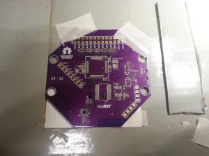
First off I downloaded Design Spark, which is the PCB editor the OpenBCI designs were made with. I used it to generate gerber files for getting the boards and solder paste stencils manufactured by OSH Park. By now they even have a function for importing Design Spark files.
Anyway, here are the Gerber files for the OpenBCI V3 8bit board. You should be able to place OSH orders using these:
OpenBCI 8bit OSH Park
For OSH Stencils:
OpenBCI 8bit OSH Stencils working
32bit Gerbers:
OpenBCI 32bit
32bit board stencil Gerbers:
OpenBCI 32bit Stencil
Daisy Board Gerbers (the 8bit board stencil partially fits the Daisy board, therefore I didn’t generate stencil Gerbers for that):
OpenBCI_Daisy

Note that there’s a bug on the Daisy PCB, which is described here.
luckily I knew about that issue and fixed it during the “pick and place” process prior to soldering.

I would recommend building the 32bit version right away since it is more capable (writes to SD, can be upgraded to 16 channels, fewer power rails, runs from one lithium cell, no need for 5V+, better microcontroller and last but not least: easier to build since it has fewer parts!).

Most parts were sourced from Digikey and Mouser. The SD card holder I found somewhere on ebay.
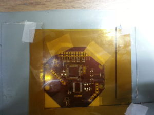
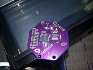
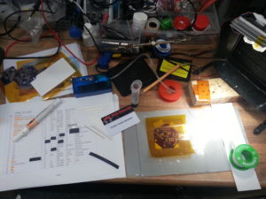
Also, I found picking and placing of tiny 0402 parts worked best with my DIY SMD vacuum tool and a thin needle. Especially where the components are densely packed (below the ADS1299) this method was very helpful. Before you begin, make sure to print out the OpenBCI_32bit_BOM and stick the component tapes with gluestick or sticky tape right next to the part indices. That way no parts get lost and you know exactly where each one belongs.

20160613_163743

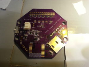
20160613_164020

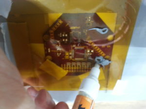
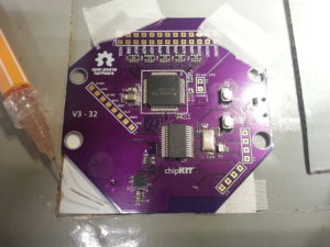
I had better results adding a drop a thin flux from a flux pen into the solder paste and mixing it. That way the solder paste is a bit smoother and reflows better. Remember: you can never use too much flux!

20160613_164152

20160613_164534

20160613_170951

The top side goes into the DIY reflow oven

20160613_171929

The bottom side is soldered with a hot air tool, being careful not to overheat the PCB.

20160613_175840

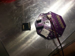
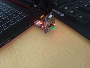
I’ve soldered 1.27mm header pins to the RFduino and female headers to the PCB because the wireless link is the bottleneck of the system. The headers allow to connect a different wireless module such as BT 2.1 or a USB-serial converter, which could be useful when planning to increase the sampling rate or using the system with Android devices.

20160613_185014

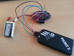
Using the PICKIT 3 programmer and MPLAB IPE (you can install ithe IPE without installing the IDE) to flash the Chipkit bootloader (can be found in the OpenBCI Github repository).

20160613_191010

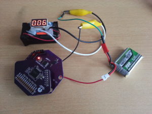
The current draw of the 32bit board is about 60 mA

20160614_105347

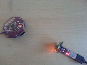
My own dongle design:

20160614_105403

20160613_193246

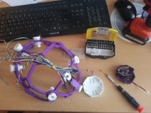
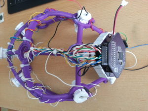
Time to print the headware (“Ultracortex Nova/Supernova”)

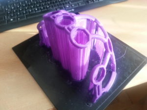
The print was done on an Ultimaker 2 clone with the recommended slicer settings and turned out ok. It took about 12 hours and I experienced some problems while printing the first half. Some parts snapped off because the print head collided with plastic that was bending up during cooldown. This happened only during a few layers of the print (approx after one third) because the structure was not stable enough at that stage. I could repair the broken parts by filling the defects with hot glue.  When printing the second half I had an eye on the process and coud prevent that from happening.

20160616_075440

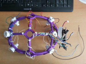
Used old PC tower cables to do the wiring. They were done in twisted pairs. All left electrodes are white and all right electrodes are colour-coded. That way you don’t need that many colors and nevertheless finding the corresponding electrode is easy.

20160617_103454

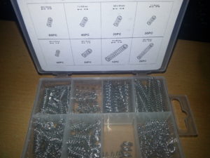
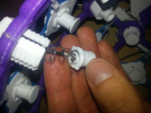
There are spring sets sold on the usual trading platform that contain the necessary springs to build the electrode inserts. The one below contains the “weak” as well as the “strong” spring for the “dummy inserts”. The weak spring had to be pulled apart a few mm to fit better.

20160701_092408

20160617_110640

20160617_145008

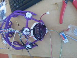
As you can see, I soldered the header of the Daisy board on the bottom side which takes up less space.

20160617_164954

OpenBCI parts <–this zip file contains my snap-on lid design that also covers the Daisy board as well as the earclip electrode design. Both parts can be found on Thingiverse as well:

http://www.thingiverse.com/thing:1635759

http://www.thingiverse.com/thing:1648317

20160620_080217

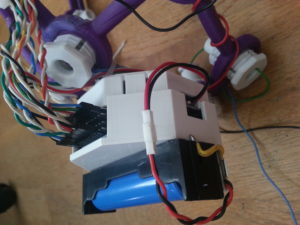
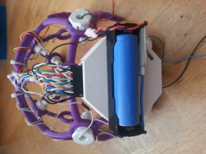
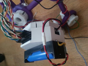
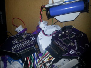
An 18650 holder with TP4056-based protection and charging circuit was placed on top to have a reliable power supply.

cover_on_daisy1

cover_on_daisy2

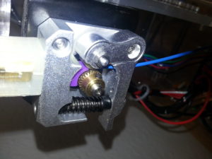
What you’re not being told: you have to print the “QUADSTAR” parts of the Ultracortex Nova/Supernova in PLA SOFT or any other elastomer filament. I had to modify my Prusa i3 extruder to prevent the soft 1.75 mm filament from kinking before entering into the bowden tube. This part fixes the issue: http://www.thingiverse.com/thing:1652091

Also I found that I had to turn off retractions because as soon as the filament passes the extruder drivewheel, it gets compressed and shoud not undergo this process twice because then it gets too damaged to be pushed into the bowden tube and extrusion simply stops at that point. Pain.

20160630_094022

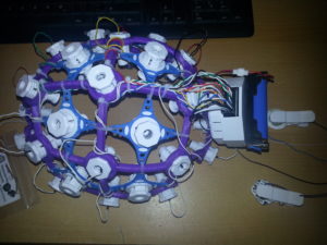
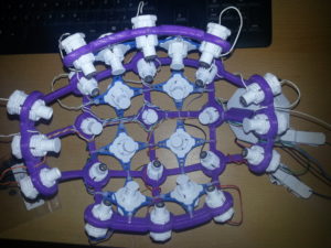
Finished Iron Maiden, err…. I mean Ultracortex, wired for the 16 channel standard configuration according to the Processing GUI with as many “comfy inserts” as possible.

20160630_195026

20160630_195049

20160630_201633

One thing I noticed after using the Disposable / Reusable Dry EEG Electrode [TDE-200] was instant corrosion. Not that surprising given that two different metals (stainless steel M2 bolt and Ag/AgCl surface) come in contact. As you can see on the picture below on the left electrode the AgCl layer corroded away to that extent after only one day. As a comparison there’s a fresh electrode on the right. The only solution I see at the moment is to attach the electrodes only if they are needed.

20160701_081452

A slight modification was done to be able to add/remove electrodes more quickly: the electrode cables were soldered directly to the M2 nuts and superglued to the back of the electrode holder, so the nut stays attached to the plastic part even if there is no bolt pressing it down.

20160630_200402

Results:

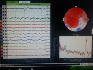
Rocording with my eyes closed. Note the alpha peak in the FFT plot. As you can see not all channels are working. It’s not that easy getting 16 dry electrodes to work. I’m also having issues with channel 2 for some reason. Maybe there’s a bad solder joint somewhere on the PCB.

20160630_194627

Conclusions:

The OpenBCI V3 32bit + Daisy is a clean design and a good way to get 16 channels of electrophysiological data up and running and a great pplication for the ADS1299. The documentation is definitely good enough to build everything yourself, assuming you have some experience with SMT soldering. The DIY approach is also cheaper. I think you can get away with one third the price for the 32bit board and Daisy module, not including the cost of your labour of course. It’s a challenging project, but for me it was worth the effort. The DIY approach gives you the possibility to modify the design if you need to. I would like to use the potential of the ADS1299 more in the future and for example increase the sampling rate.
When it comes to the headware, my initial fascination faded a little when I discovered that the Ultracortex is quite painful to wear! The comb electrodes are no pleasure on your skin, let me tell you! But they do provide good signal quality almost instantaneously. The corrosion issue is also a significant one. I’m wondering how the signal quality changes as soon as the AgCl layer is gone completely. Maybe there’s a way of re-applying the layer by electrolysis in NaCl solution. This remains subject of further investigation. Other that those insights I find the design of the Ultracortex amazing! It’s a perfect example of great design specifically for 3D printing. Everything fits together perfectly well and looks great! Many thanks to the OpenBCI team for making their great work open source!



Plot Clock w/ DS1307 RTC


plot clock w/ RTC


plot clock


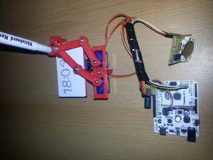
I’ve printed the parts for a Plot Clock in PLA and assembled it in a pretty much standard configuration, which worked great. Quite a bit of filing and sanding was necessary, but it was worth it, the final device was quite easy to calibrate. The only thing I found was missing is time keeping capability, so I added a DS1307 I2C real time clock module, which is a straightforward procedure. Learn how to set up the RTC HERE.
Before you run the sketch that sets the time on the RTC, make sure to remove the battery once to reset the DS1307. Put the battery back in and run the sketch. My modification on the Plot Clock code simply fetches the time once every time you power the arduino up. Further timekeeping is done by the ATmega.


// Plotclock
// cc - by Johannes Heberlein 2014
// v 1.01
// thingiverse.com/joo   wiki.fablab-nuernberg.de

// units: mm; microseconds; radians
// origin: bottom left of drawing surface

// time library see http://playground.arduino.cc/Code/time 

// Date and time functions using a DS1307 RTC connected via I2C and Wire lib
     
    #include <Wire.h>
    #include "RTClib.h"
     
    RTC_DS1307 RTC;
    
// delete or mark the next line as comment when done with calibration  
//#define CALIBRATION

// When in calibration mode, adjust the following factor until the servos move exactly 90 degrees
#define SERVOFAKTOR 555

// Zero-position of left and right servo
// When in calibration mode, adjust the NULL-values so that the servo arms are at all times parallel
// either to the X or Y axis
#define SERVOLEFTNULL 2075
#define SERVORIGHTNULL 1065

#define SERVOPINLIFT  2
#define SERVOPINLEFT  3
#define SERVOPINRIGHT 4

// lift positions of lifting servo
#define LIFT0 1350 // on drawing surface
#define LIFT1 1180// between numbers
#define LIFT2 850  // going towards sweeper

// speed of liftimg arm, higher is slower
#define LIFTSPEED 1500

// length of arms
#define L1 35
#define L2 55.1
#define L3 13.2


// origin points of left and right servo 
#define O1X 22
#define O1Y -25
#define O2X 47
#define O2Y -25


#include <Time.h> // see http://playground.arduino.cc/Code/time 
#include <Servo.h>

int servoLift = 1500;

Servo servo1;  // 
Servo servo2;  // 
Servo servo3;  // 

volatile double lastX = 75;
volatile double lastY = 47.5;

int last_min = 0;

void setup() 
{ 
  
  Wire.begin();
  RTC.begin();
  DateTime now = RTC.now();
  // Set current time only the first to values, hh,mm are needed
  int rhour = now.hour();
  int rminute = now.minute();
  setTime(rhour,rminute,0,0,0,0);

  drawTo(75.2, 47);
  lift(0);
  servo1.attach(SERVOPINLIFT);  //  lifting servo
  servo2.attach(SERVOPINLEFT);  //  left servo
  servo3.attach(SERVOPINRIGHT);  //  right servo
  
  delay(1000);
  

} 

void loop() 
{ 

#ifdef CALIBRATION

  // Servohorns will have 90° between movements, parallel to x and y axis
  drawTo(-3, 29.2);
  delay(500);
  drawTo(74.1, 28);
  delay(500);

#else 
  //DateTime now = RTC.now();
  
  int i = 0;
  if (last_min != minute()) {

    if (!servo1.attached()) servo1.attach(SERVOPINLIFT);
    if (!servo2.attached()) servo2.attach(SERVOPINLEFT);
    if (!servo3.attached()) servo3.attach(SERVOPINRIGHT);

    lift(0);
    
    hour();
    
    
    while ((i+1)*10 <= hour())
    {
      i++;
    }

    number(3, 3, 111, 1);
    number(5, 25, i, 0.9);
    number(19, 25, (hour()-i*10), 0.9);
    number(28, 25, 11, 0.9);

    i=0;
    while ((i+1)*10 <= minute())
    {
      i++;
    }
    number(34, 25, i, 0.9);
    number(48, 25, (minute()-i*10), 0.9);
    lift(2);
    drawTo(74.2, 47.5);
    lift(1);
    last_min = minute();

    servo1.detach();
    servo2.detach();
    servo3.detach();
  }

#endif

} 

// Writing numeral with bx by being the bottom left originpoint. Scale 1 equals a 20 mm high font.
// The structure follows this principle: move to first startpoint of the numeral, lift down, draw numeral, lift up
void number(float bx, float by, int num, float scale) {

  switch (num) {

  case 0:
    drawTo(bx + 12 * scale, by + 6 * scale);
    lift(0);
    bogenGZS(bx + 7 * scale, by + 10 * scale, 10 * scale, -0.8, 6.7, 0.5);
    lift(1);
    break;
  case 1:

    drawTo(bx + 3 * scale, by + 15 * scale);
    lift(0);
    drawTo(bx + 10 * scale, by + 20 * scale);
    drawTo(bx + 10 * scale, by + 0 * scale);
    lift(1);
    break;
  case 2:
    drawTo(bx + 2 * scale, by + 12 * scale);
    lift(0);
    bogenUZS(bx + 8 * scale, by + 14 * scale, 6 * scale, 3, -0.8, 1);
    drawTo(bx + 1 * scale, by + 0 * scale);
    drawTo(bx + 12 * scale, by + 0 * scale);
    lift(1);
    break;
  case 3:
    drawTo(bx + 2 * scale, by + 17 * scale);
    lift(0);
    bogenUZS(bx + 5 * scale, by + 15 * scale, 5 * scale, 3, -2, 1);
    bogenUZS(bx + 5 * scale, by + 5 * scale, 5 * scale, 1.57, -3, 1);
    lift(1);
    break;
  case 4:
    drawTo(bx + 10 * scale, by + 0 * scale);
    lift(0);
    drawTo(bx + 10 * scale, by + 20 * scale);
    drawTo(bx + 2 * scale, by + 6 * scale);
    drawTo(bx + 12 * scale, by + 6 * scale);
    lift(1);
    break;
  case 5:
    drawTo(bx + 2 * scale, by + 5 * scale);
    lift(0);
    bogenGZS(bx + 5 * scale, by + 6 * scale, 6 * scale, -2.5, 2, 1);
    drawTo(bx + 5 * scale, by + 20 * scale);
    drawTo(bx + 12 * scale, by + 20 * scale);
    lift(1);
    break;
  case 6:
    drawTo(bx + 2 * scale, by + 10 * scale);
    lift(0);
    bogenUZS(bx + 7 * scale, by + 6 * scale, 6 * scale, 2, -4.4, 1);
    drawTo(bx + 11 * scale, by + 20 * scale);
    lift(1);
    break;
  case 7:
    drawTo(bx + 2 * scale, by + 20 * scale);
    lift(0);
    drawTo(bx + 12 * scale, by + 20 * scale);
    drawTo(bx + 2 * scale, by + 0);
    lift(1);
    break;
  case 8:
    drawTo(bx + 5 * scale, by + 10 * scale);
    lift(0);
    bogenUZS(bx + 5 * scale, by + 15 * scale, 5 * scale, 4.7, -1.6, 1);
    bogenGZS(bx + 5 * scale, by + 5 * scale, 5 * scale, -4.7, 2, 1);
    lift(1);
    break;

  case 9:
    drawTo(bx + 9 * scale, by + 11 * scale);
    lift(0);
    bogenUZS(bx + 7 * scale, by + 15 * scale, 5 * scale, 4, -0.5, 1);
    drawTo(bx + 5 * scale, by + 0);
    lift(1);
    break;

  case 111:

    lift(0);
    drawTo(70, 46);
    drawTo(65, 43);

    drawTo(65, 49);
    drawTo(5, 49);
    drawTo(5, 45);
    drawTo(65, 45);
    drawTo(65, 40);

    drawTo(5, 40);
    drawTo(5, 35);
    drawTo(65, 35);
    drawTo(65, 30);

    drawTo(5, 30);
    drawTo(5, 25);
    drawTo(65, 25);
    drawTo(65, 20);

    drawTo(5, 20);
    drawTo(60, 44);

    drawTo(75.2, 47);
    lift(2);

    break;

  case 11:
    drawTo(bx + 5 * scale, by + 15 * scale);
    lift(0);
    bogenGZS(bx + 5 * scale, by + 15 * scale, 0.1 * scale, 1, -1, 1);
    lift(1);
    drawTo(bx + 5 * scale, by + 5 * scale);
    lift(0);
    bogenGZS(bx + 5 * scale, by + 5 * scale, 0.1 * scale, 1, -1, 1);
    lift(1);
    break;

  }
}


void lift(char lift) {
  switch (lift) {
    // room to optimize  !
  case 0: //850

      if (servoLift >= LIFT0) {
      while (servoLift >= LIFT0) 
      {
        servoLift--;
        servo1.writeMicroseconds(servoLift);				
        delayMicroseconds(LIFTSPEED);
      }
    } 
    else {
      while (servoLift <= LIFT0) {
        servoLift++;
        servo1.writeMicroseconds(servoLift);
        delayMicroseconds(LIFTSPEED);

      }

    }

    break;

  case 1: //150

    if (servoLift >= LIFT1) {
      while (servoLift >= LIFT1) {
        servoLift--;
        servo1.writeMicroseconds(servoLift);
        delayMicroseconds(LIFTSPEED);

      }
    } 
    else {
      while (servoLift <= LIFT1) {
        servoLift++;
        servo1.writeMicroseconds(servoLift);
        delayMicroseconds(LIFTSPEED);
      }

    }

    break;

  case 2:

    if (servoLift >= LIFT2) {
      while (servoLift >= LIFT2) {
        servoLift--;
        servo1.writeMicroseconds(servoLift);
        delayMicroseconds(LIFTSPEED);
      }
    } 
    else {
      while (servoLift <= LIFT2) {
        servoLift++;
        servo1.writeMicroseconds(servoLift);				
        delayMicroseconds(LIFTSPEED);
      }
    }
    break;
  }
}


void bogenUZS(float bx, float by, float radius, int start, int ende, float sqee) {
  float inkr = -0.05;
  float count = 0;

  do {
    drawTo(sqee * radius * cos(start + count) + bx,
    radius * sin(start + count) + by);
    count += inkr;
  } 
  while ((start + count) > ende);

}

void bogenGZS(float bx, float by, float radius, int start, int ende, float sqee) {
  float inkr = 0.05;
  float count = 0;

  do {
    drawTo(sqee * radius * cos(start + count) + bx,
    radius * sin(start + count) + by);
    count += inkr;
  } 
  while ((start + count) <= ende);
}


void drawTo(double pX, double pY) {
  double dx, dy, c;
  int i;

  // dx dy of new point
  dx = pX - lastX;
  dy = pY - lastY;
  //path lenght in mm, times 4 equals 4 steps per mm
  c = floor(4 * sqrt(dx * dx + dy * dy));

  if (c < 1) c = 1;

  for (i = 0; i <= c; i++) {
    // draw line point by point
    set_XY(lastX + (i * dx / c), lastY + (i * dy / c));

  }

  lastX = pX;
  lastY = pY;
}

double return_angle(double a, double b, double c) {
  // cosine rule for angle between c and a
  return acos((a * a + c * c - b * b) / (2 * a * c));
}

void set_XY(double Tx, double Ty) 
{
  delay(1);
  double dx, dy, c, a1, a2, Hx, Hy;

  // calculate triangle between pen, servoLeft and arm joint
  // cartesian dx/dy
  dx = Tx - O1X;
  dy = Ty - O1Y;

  // polar lemgth (c) and angle (a1)
  c = sqrt(dx * dx + dy * dy); // 
  a1 = atan2(dy, dx); //
  a2 = return_angle(L1, L2, c);

  servo2.writeMicroseconds(floor(((a2 + a1 - M_PI) * SERVOFAKTOR) + SERVOLEFTNULL));

  // calculate joinr arm point for triangle of the right servo arm
  a2 = return_angle(L2, L1, c);
  Hx = Tx + L3 * cos((a1 - a2 + 0.621) + M_PI); //36,5°
  Hy = Ty + L3 * sin((a1 - a2 + 0.621) + M_PI);

  // calculate triangle between pen joint, servoRight and arm joint
  dx = Hx - O2X;
  dy = Hy - O2Y;

  c = sqrt(dx * dx + dy * dy);
  a1 = atan2(dy, dx);
  a2 = return_angle(L1, (L2 - L3), c);

  servo3.writeMicroseconds(floor(((a1 - a2) * SERVOFAKTOR) + SERVORIGHTNULL));

}

More mods on the Velleman k8200 3D Printer

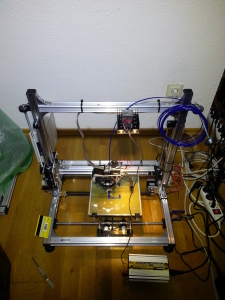
k8200


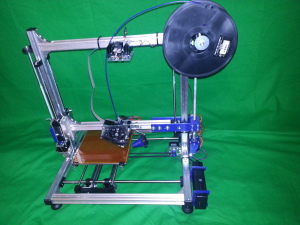
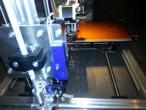
After using the Printer for some weeks, some weaknesses became apparent and I finally had the motivation to fix them and add some robustness to the system and increase precision.


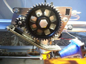
1. Add a dirt catcher under the extruder gears to prevent the dirty particles composed of ABS debris and oil from dropping on the printing bed.


20141022_145746


2. replace the X-Axis pulley with a printed one, since the original one was out of round, which impairs printing quality!


pulley (1)


3. Add robust and precise homing system for the Z axis.


z homing system


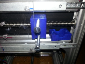
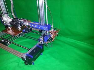
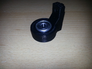
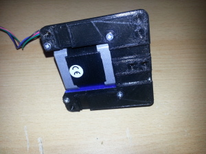
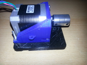
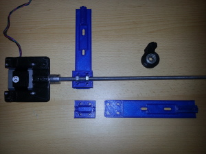
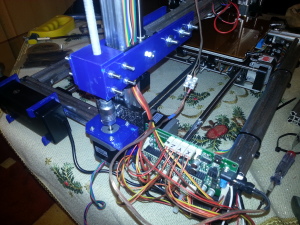
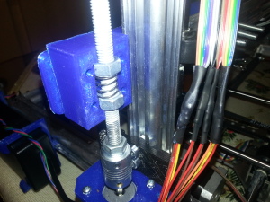
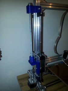
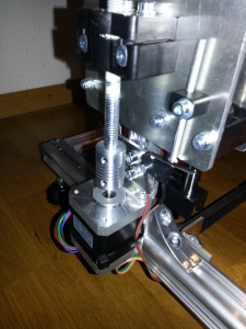
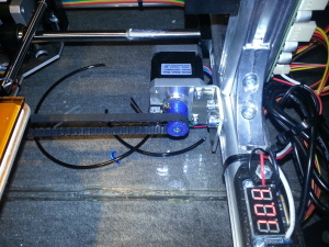
4. Extend the Z- Axis with a second spindle. I’m using another M8 stainless steel threaded rod with a flex shaft coupler and 2 regular hex nuts with anti-backlash spring. The motor mount and 608Z ball bearing holder are 3D-printed, as well as the arm extension. I’m not sure how this will affect print quality, but adding another spindle prevents the other one from wearing quickly. Also, like many other people, I have observed stronger vibration of the Z arm than on the frame itself. Eliminating it is not that hard and I had another NEMA 17 stepper and all the other parts lying around here anyway. My design can be found here.


k8200 dual z axis


bearing holder z-axis


motor mount side view


motor mount z-axis


printed z axis arm extension and nut box


second z axis complete assembly


anti-backlash nut assembly


k8200 (3)


5: rebuild the left Z axis with more rigid parts:


Left Z axis anti-backlash and more rigid mount


Z-axis Backlash eliminator


K8200 rod guide piecesholder STL can be found here


6. Mount a proper filament guide with a ball bearing on top of the LED light. This is supposed to have a very interesting function: since my printer lives in the attic, the filament tends to break, especially PLA is affected, during printing and when the filament spool is almost empty. The reasons are 1. low temperature and 2. tension in the filament as it unwinds from a smaller radius (the windings near to the core of the spool have a smaller radius). Before I begin printing something, I will turn on the nice 12W LED lamp which produces a lot of heat as a by-product. Since the filament makes its sharpest turn on its way into the extruder right where the heatsink of the LEDs is located, this is exactly the place where heat is needed. I hope that this will make filament shattering more unlikely in the future.


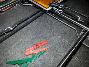
7. Add belt tensioners to the X and Y axis belts. these are simply springs from standard plastic clothespins that are bent to a proper shape, attached to the belts and secured with small zip ties. Watch out that the belts do not touch each other.


belt tensioners


8. Add a filament spool holder with ball bearings. Maybe this will take off strain from the filament as well and prevent it from breaking due to the spool spinning unevenly.
here’s the thing


To do in the near future:


9. Update the firmware


10. Add an SD card holder, rotary encoder and a 20×4 LCD


11. make an enclocure for the elctronics


12. attach little heatsinks to the stepper driver chips


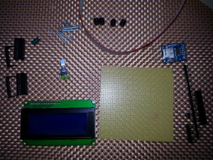
parts for the autonomous board (k8200/3drag)


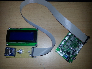
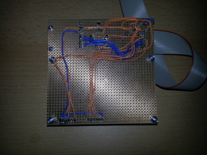
After realizing that a 20×4 character lcd, a (micro) SD card adapter with level shifter, a rotary encoder, 2×10 male & female pin headers and a ribbon cable is all that’s needed for transforming the printer into an autonomous device, I could finally start hacking again, because I had most parts lying around here anyway. What seemed to be a simple task, quickly turned out to become a little life lesson.
Since the K8200 Velleman kit is derived from an open source, RepRap-inspired project named 3DRAG by www.open-electronics.org, all schematics are freely accessible and its hardware as well as software are quite universal. Here’s the page with the schematics for the “autonomous board” that connects to the 2×9 pin header on the k8200/3DRAG control board. The schematics are quite simple, albeit not quite readable. Nontheless I soldered some pins onto the main board and started soldering up the LCD/SD/encoder board on a perfboard, which can sometimes take some hours if you wat a clean assembly.


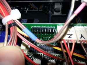
2x9 header pins soldered on the k8200/3drag control board


The excitement of getting the system to work as quickly as possible and improving the project forced me to overcome tiredness and hypoglycemia and in the end led to me swapping some dangerous wires, to be exact the motor supply voltage pin with some other port pin of the Atmega2560 microcontroller. Well, you can imagine what happened as the chip got 15 Volts on on of its GPIO pins! It died immediately. Before it died, I managed to do a firmware update though, which worked without any problems. Just short the “JPROG” pins together with a jumper and treat the thing like a regular Arduino Mega (with power supply connected, else it won’t upload). So this is what I ended up with:


control board and motherboard k8200 3drag


control board bottom (1)


I’m hoping that the FTDI chip and the stepper motor drivers have survived this terrible accident. The FTDI chip is at least recognized by the PC as a serial port device, I haven’t tested the stepper drivers yet. As for now I’ve removed the broken microcontroller chip and will try to replace it to see if the main board can be resuscitated. Having to de-solder re-solder a TQFP100 package is god’s punishment for being impatient and not taking a break during my build.
If replacing the microcontroller, flashing the Arduino Mega bootloader and Marlin v2 firmware doesn’t bring the main board back to life, I will probably have to install a RAMPS 1.4 electronics. This is basically the same electronics as the Original K8200/3DRAG mainboard, but a little more versatile, albeit a little less compact. They are available on eb** in various combinations. You have the possibility to connect a 128×64 graphics lcd and even a bluetooth module to the RAMPS 1.4 board, so this little crisis can even bring some new options as the ancient chinese saying states 🙂
Right now, I’ve corrected the bug in the wiring of the LCD/SD/encoder board and keep waiting for replacement parts.


Update: ok, so replacing the microcontroller didn’t resuscitate the board. I suspect that the stepper drivers and something else got fried as well. Actually not that surprising, as far as I have reconstructed the scenario correctly, 15VDC with reversed polarity might have hit the logic supply rails. After soldering the Atmega2560 I was not even able to flash the bootloader. Despite using plenty of flux and producing neat-looking solder joints nothing seemed to work. The chip was supposed to have the wrong signature according to avrdude. I tried overriding that error and doing the upload anyway, but that didn’t yield any results at all. Not even the fuse and lock bits could be configured. After touching all pins with the soldering iron once again to make sure that there are no “cold” solder joints and removing all stepper drivers, a different error was displayed. “Device doesn’t answer…” After a while I gave up and ordered a complete RAMPS kit with a RepRapDiscount Full Graphic Smart Controller and a complete set of new stepper drivers. Maybe I’ll try tracing down the error, but not right now 🙂 I’ll open up a new blogpost on the RAMPS setup on the k8200.

Velleman k8200 Assembly, Mods and Review

3D printing can greatly fuel the creativity and capabilities of a passionate maker. I thought that quite some time ago when I encountered the RepRap project. I was building my CNC machine back then and wondered whether it was possible to add 3D printing capability to it. Some people have tried building 3D printers using threaded rods/trapezoidal rods and claimed that it leads nowhere, since the motion is too slow. The approach was called RepStrap. I dropped the idea immediately and decided to wait some time until the RepRap project becomes mature enough to build a safe and reliable machine, since I knew how exhausting the world of CNC can be from my own laser engraver/mill project.


When the Velleman k8200 kit appeared on the market, I fell in love with it. The frame was composed of the same aluminum profiles as I’ve been using in my CNC and so I could guess that the kit had some potential. When the price finally dropped to almost the price of the bare parts, I decided to finally go for it.
The assembly of the kit was extremely interesting. The assembly manual is very detailed and guides you through even the finest details. It took me one day of full-time work for the mechanics and one day full-time for the electrical connections. Being quite experienced with soldering I would nontheless say that it was quite challenging. The insulation of the ribbon cable is not easy to remove. You better use simple schissors to accomplish that and be sure to thoroughly tin the wires, since the chance of producing a loose connection is pretty high given that there are that many solder joints.
I added some modifications right away, because I already knew about some weaknesses of the kit:


1. Installing this flex shaft coupler


2. Installing a 21,5cm x 21,5cm glass plate on the heat bed with 4 clipboard clips. The heatbed is a thin PCB that is supposedely impossible to get even. In the middle it is higher than at the edges, so I haven’t even tried printing directly on the PCB and pressed the ~2mm thick glass on top.


3. Covering the glass plate with Kapton Tape (polyimide tape). This tape is heat-resistant and due to the stronger Van Der Waal’s forces the workpiece sticks perfectly to the printing bed, stil being easily removable. When printing on plain glass small prints might work ok, but with large prints the edges tend to bend up and the whole workpiece sometimes comes off and is ruined.


4. Terminal blocks to connect the heatbed and thermistor.


5. Added an M8 washer to the Z axis nut since it had some play in its plastic mount that was eliminated that way.


6. The extruder connections are made using standard 2,54mm male/female pin headers so that they can be disconnected easily without the need to remove the heatshrink tubing and cutting wires in case you want to change something.


7. Put 4x Luxeon Rebel Star LEDs on the top profile. The light acts as a filament guide as well 🙂


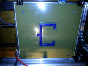
After downloading Repetier Host 0.95 from the Velleman homepage and calibrating the axes as described in the construction manual, the first print was attempted. I cleaned the glass surface with ethanol and printed two of these with satisfying results right away.
It’s a good idea to print something small in the beginning and not the huge enclosure as Velleman suggests. When your PLA doesn’t want to stick to the printing bed you might have to adjust the Z axis again (further minimize the gap). When the distance is right, the PLA should stick to clean glass. Even with the new PLA profile as offered on the download page. I made no modifications to parameters whatsoever. With Kapton Tape on the printing bed things work perfectly.


My conclusion is a very positive one. The k8200 kit is very well-documented and assembles easily. The printer is also customizable, since the aluminum profiles can be bought in some hardware stores. Some soldering skills are requred though! If you feel confident about that and invest about 10€ in some minor modifications as described above you get a reliable machine for currently the lowest price on the market.


k8200 printing


k8200 power supply bracket


finished power supply brackets


aluminum flex shaft coupler on the Z axis


Velleman k8200 first print