Category Archives: Physics

Physics experiments and power systems such as electromagnetic accelerators, tesla coils, HV experiments

Semi-Automatic Spot Welder

Sometimes I feel the need for a spot welder for welding battery tabs. Since soldering batteries can damage their chemistry and commercial spot welders are too expensive, I decided to build my own from scrap. I don’t recommend doing this if you are not confident with electrical stuff since this project ivolves mains voltage and high currents which result in an overall power of around 1000W! You have been warned!


Microwave oven transformers (MOTs) can be obtained for free and have great potential to be used or abused in various projects. One popular use of MOTs is in DIY spot welders. One has to remove the secondary (high voltage) winding and sqeeze in 2-3 turns of heavy gauge copper wire in order to get 1.5-3V @ ca. 400A. There is an infinite amount of information on how to do this online so I won’t cover it too deeply.
I was able to squeeze 2.5 turns onto the core using ca. 8mm thick stranded copper wire. The electrode blocks are made from pure copper (12x12x50mm copper bars) to minimize resistance and sink the heat. The lugs that connect the wire to the blocks can be made from copper sheets or copper pipe. The welding electrodes are 4.5mm solid copper wire with pointed tips. I had to experiment a little with electrode distance and tip geometry. 3-10mm distance and round tip geometry are probably good starting points.


In order to get consistent welds, some parameters have to be controlled with the most important being mechanical force of the electrode to the workpiece and duration of the high current pulse. The idea behind resistance spot welding is that the spots where electrodes touch the workpiece are the areas of highest electrical resistance and therefore they heat up, melt and fuse together. My welder is built in a “series configuration” which means that both electrodes are at the top as opposed to the alternative variant where one is at the top end the other at the bottom. It is important for both welding electrodes to have near-equal mechanical force on the workpiece and therefore both are spring-loaded individually. Two microswitches in series ensure that the same force on every electrode is applied every time. Only when both microswitches are triggered, the welding pulse is applied. Afterwards the system waits for some seconds until the next weld can be performed. Note that the cable tie on the pictures only holds both arms together losely. They are still able to move away from each other for at least 10mm which is sufficient.


An Attiny85 breakout board takes care of pulse timing. The pulse duration can be adjusted with a 5k potentiometer. A TM1637-based 4 digit 7 segment display shows its duration in milliseconds. A solid state relay for AC voltage turns on the MOT for the set duration. The control circuit is powered by a small 5V 1A AC-DC converter of asian origin. All GPIO pins of the Tiny are finally occupied. The Attiny85 was programmed using the Arduino IDE and while the code is primitive, it does its job well:


//Spot welder controller, simple "blocking code using delays
//uses TM1637 4digit LED display board
//D2: data, D1: clock of TM1637
//D0: solid state relay to switch the MOT
//A3: potentiometer (5k to 50k)
//D4: trigger (2 microswitches in series for each welding electrode)


#include <Arduino.h>
#include <TM1637Display.h>

// Module connection pins (Digital Pins)
#define CLK 1
#define DIO 2
#define SSR 0
#define POT A3
#define TRIG 4

#define maxPulseLength 500

int weldingTimer = 400; //in ms
int pauseTimer = 4000;
int addr=0;
TM1637Display display(CLK, DIO);

void setup() {
  display.setBrightness(7);
  pinMode(TRIG, INPUT_PULLUP);
  pinMode(SSR, OUTPUT);
  digitalWrite(SSR,LOW);
  //value = EEPROM.read(addr);
}

void loop() {
  int anVal = analogRead(POT);
  weldingTimer=map(anVal,0,1024,0,maxPulseLength);
  display.showNumberDec(weldingTimer);

  if(digitalRead(TRIG)==LOW){
    digitalWrite(SSR,HIGH);
    delay(weldingTimer);
    digitalWrite(SSR,LOW);
    delay(pauseTimer);
  }
}

This system has plenty of power. It’s probably even over-powered for battery tab welding so make sure to start with small welding pulses of around 20ms and increase until the weld sticks well. With 70ms and an electrode distance of 3mm I managed to burn a hole through an empty coin cell in an attempt to weld a 0.1mm nickel strip to it. Experiment on scrap metal before you proceed to serious business such as 18650 cells.

Ebay 500W Wind Generator

Recently I’ve come across this high quality device while looking for a permanent magnet alternator to experiment with.
It’s supposed to be a generator designed particularly for wind turbines and able to deliver 500W. Not bad. Its weight is about 3.5kg. The shaft diameter is 20mm. That’s about all info I could get from the seller.


20161029_100500


The inner shaft diameter is 12mm, the 20mm slotted steel adapter can be taken off. It is sealed off with a plastic “bearing” with a steel spring around it (not visible in the picture). Could be polyethylene or similar to protect it from the elements. The chassis is supposedly cast aluminium at the front and a precision machined Al cover at the back with a chunky rubber ring between back cover and alternator. The alternator itself is a 90mm diameter high quality brushless outrunner motor/alternator by CPM with the entire stator potted in some kind of plastic. The rotor was made from machined steel. After visiting the webpage on the label you get forwarded to http://www.cpmotion.com/ A quick search for the part number was not successful.


20161029_095037


20161029_095149


The injection molded black plastic cover prevents the cables to touch the rotor of the alternator. Nice attention to detail. The black connector on the ribbon cable I have attached myself because I had a 20pin one lying around and 0.1 inch headers are much easier to work with.


20161029_095106


I got the thing from ebay (new and unused!) for less than 50€ and expected a 3phase device because of the three wires coming out of it. Instead it turned out to have a DC output (the yellow and green one is just tied to the chassis). After cranking it up by hand for testing I figured out that some charge was stored across the red and black wire which implied that there’s a capacitor hidden somewhere and that it had to be DC. The fact alone that the manufacturer had chosen red and black should actually be enough of a clue that it’s a DC device. Besides the power cables a 20pin connector with a ribbon cable is poking out of the enclosure as well. Asking the seller for datasheets was not successful. I was only told that it is worth much more than what I payed for it and that it’s from a company that went bankrupt. Visiting the website on the label did not give me a datasheet for this particular device either. The only thing I was able to find out is that the manufacturer (CPM) uses the CAN bus on their other products to control their devices (CAN 2.0A) besides some digital and analog pins on their control interfaces. At least something if we assume that not only the alternator but also the control electronics was designed by them.


So the only thing left is trying to reverse engineer it. After spinning the generator up with a drill you notice a very short pulse of mechanical resistance after a couple of turns. I thought maybe there is some kind of initialization routine happening after power-up. Attaching a 60W H4 automotive light bulb as a load showed that the device is definitely useful to generate DC electricity. The bulb could be brought to full brightness easily. A voltage measurement on different rpm without a load revealed that the voltage can easily go up to 48V.
After removing all screws I tried to open the front part but I couldn’t do it for some reason and therefore I decided to not do potentially irreversible stuff for now.


Instead the next reasonable step would be to crank the alternator up evenly with a drill and measure voltages on some pins. All we know to this point is that it’s likely to find a CAN interface on the header, which means that 2 pins should measure about 2.5V (depending on whether it’s 3.3V or 5V CAN) against some ground reference.
In the picture below you see the results of mapping out the interface.


20161029_094934


Indeed I was able to find -2.5V on the pins irrespective of RPM. Then I reversed polarity of my oscilloscope/multimeter and took the GND pin as a reference for further measurements. In total I was only able to find 2 pins with 2.5V which is another progress. 2 other pins had about 3.3V on them and 3 Pins had variable voltage (0-2V in my tests) depending on the RPM.


My ambition with this device is to try to communicate with it via CAN and try to repurpose its control electronics, as it seems to be well-engineered apparatus all in all. The fact that it has a pulse of resistance at startup makes it possible for this thing to have an internal, probably configurable load inside which might be used as a brake. Also I’m curious to know what kind of data it is capable to spit out. If I were the engineer, I’d probably have it measure power and RPM…let’s see. My approach will be to try to connect an Arduino via MCP2515 to the CAN pins and see whether I get any response.

Multistage Coilgun Rifle

Building something powerful and dangerous probably lies in the nature of a man. Even (or especially) some MIT professors are passionate about powerful technical devices such as chain saws 🙂 And there’s also some competition on the internet in the world’s coilgun arsenal, where devices from all over the world are sorted and several parameters can be compared with others. One major aim is to gain good efficiency, which would be around 4%, while still keeping it portable. Some years ago I wanted to enter the heavy rifle class in this league and so this project was born. Just like its little brother, this coilgun was also accepted in world’s coilgun arsenal.


This device has been in the benchtop testing for a while and I’ve been working slowly but very persistently on it. You really need a lot of patience if you want to construct something like this. All coils and transformers are hand-wound and the capacitor banks consist of 106 small caps in total. You also have to be prepared to encounter difficulties along the way and probably even burnt parts and injuries if you aren’t careful. I would not recommend you to buid a multistage coilgun if you don’t have experience in electronis! Also, dangerous voltages and dangerous flying metal parts are involved, so bear this warning in mind!


This blogpost is a documentation of the construction process:


PIC-0004


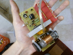
This is the capacitor charger the device is based on. The Idea and schematic for it came from uzzors2k. It is based on the Mazzilli Flyback Driver and has a lot of power and efficiency running off 12V. The secondary of the flyback transformer was re-worked with 4layers x 240 turns with 0.3mm enamelled copper wire. An adjustable coparator circuit turns the charger off when the threshold is reached.


PIC-0100


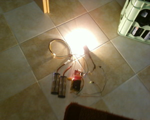
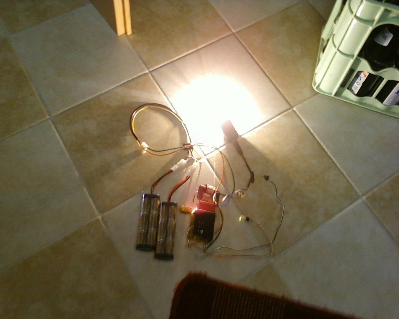
I liked this circuit so much that I’ve built 2 versions of it trying to make it more compact. Here is the socond one showing off its power: a 100W lightbulb enlightened gets pretty bright from the 14,4V NiMH batteries.


PIC-0009


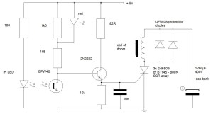
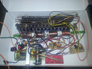
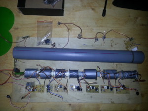
What we’ve got here is the first coil, its capacitor bank, the protection diodes and the triggering circuitry using 3 2N6509 SCRs in parallel with a 7805 for a 5V supply. The big red button is the trigger smiley


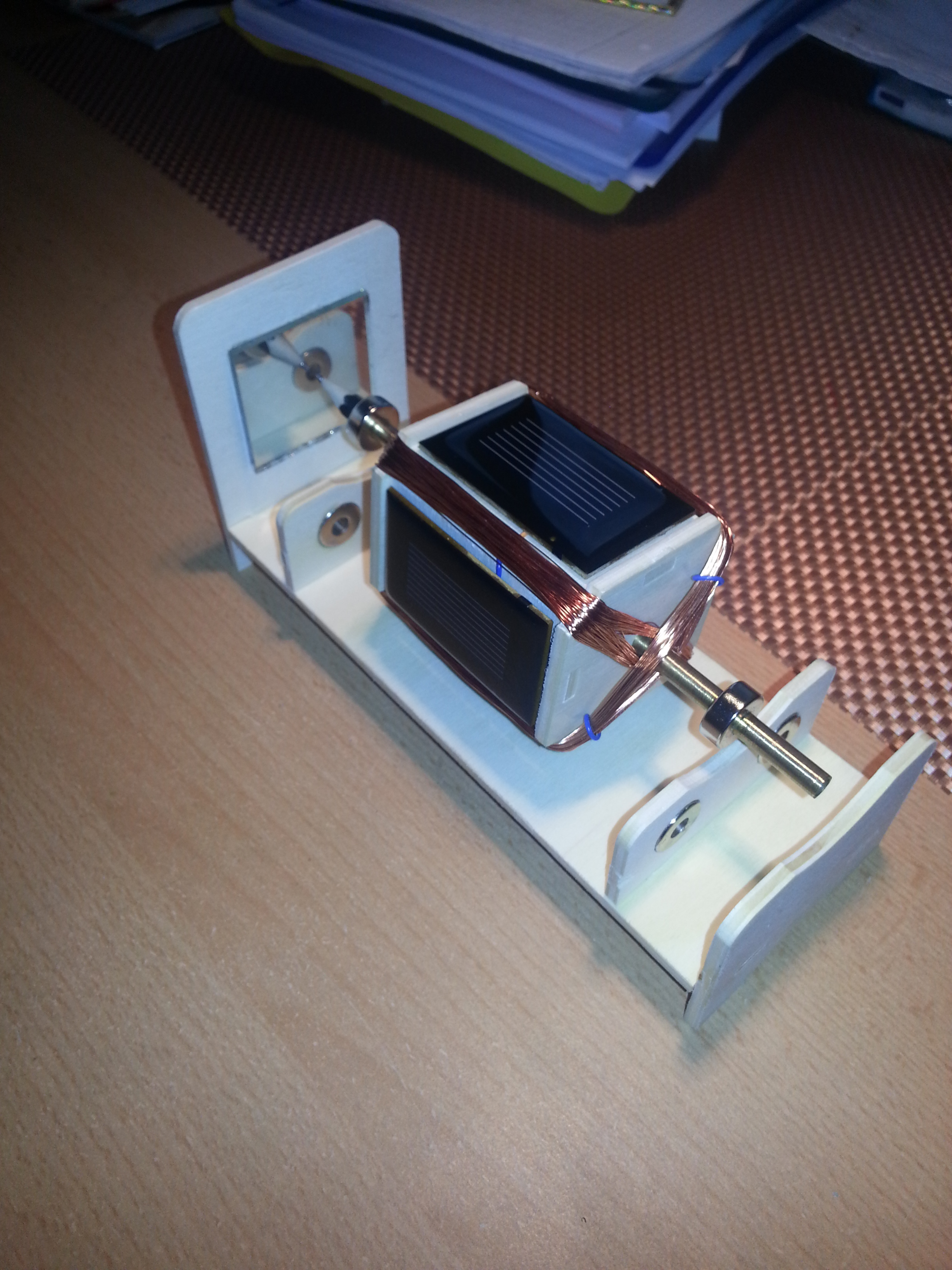
Coil data: I don’t quite remember the exact amount of turns, but it has to be something around 350 in 7 layers for the first stage, which makes the coil about 5 cm long when using 1mm wire and a cylindrical geometry. In the picture it has some more layers, which I removed in order to reduce resistance and increase efficiency when working with the chosen capacitor bank. The next coils get shorter and shorter with less and less turns for faster discharge, since all cap banks are the same size. The steel washers at each end of the coil are slotted to limit Eddy Currents.


Capacitor bank: I’ve found really cheap 68µF 400V electrolytic caps which come in packs of 10, so I’ve made banks with a total of 1088µF. They are capable of storing 87J of energy when charged to 400V.


Switching: 3x 2N6509 in parallel. Each SCR is capable of handling a surge current of 250A.


Barrell: almost transparent PVC tube with thin walls and 10mm inner diameter, originally for aquarium purposes. The light beam gets through the material without holes.


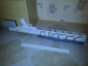
This is the Coilgun in its current stage of construction.


All 4 coils are wound, the optical detection circuits (which are the same as in my pistol) are working, all 4 stages are cooperating quite well!


trigger circuit coilgun2


As you can see each stage has got its on bridge rectifier (consisting of 4x UF4007) and 330K resistor for slow discharge in case it doesn’t get activated. 2 cap banks have got neon bulbs installed to reliably detect that they are charged even if the power supply is disconnected. The other banks will be equipped with neon bulbs as well, as soon as I get a couple of them.


20120825_224916


20120825_225002


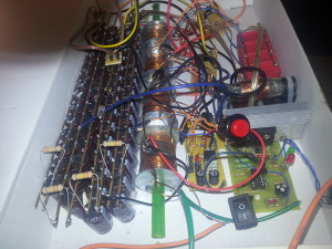
I know, I should not keep that thing that messy, because the danger of short circuits is high, but I’ll clean it up as soon as I’ve got the time.


The gun is ready to be installed into a rifle-shaped casing, but actually I’m playing with the thought of installing an additional fifth stage and add 340µF to each cap bank. This will result in 500J (!!) in total distributed on five stages. A worthy aim smiley.


Update:


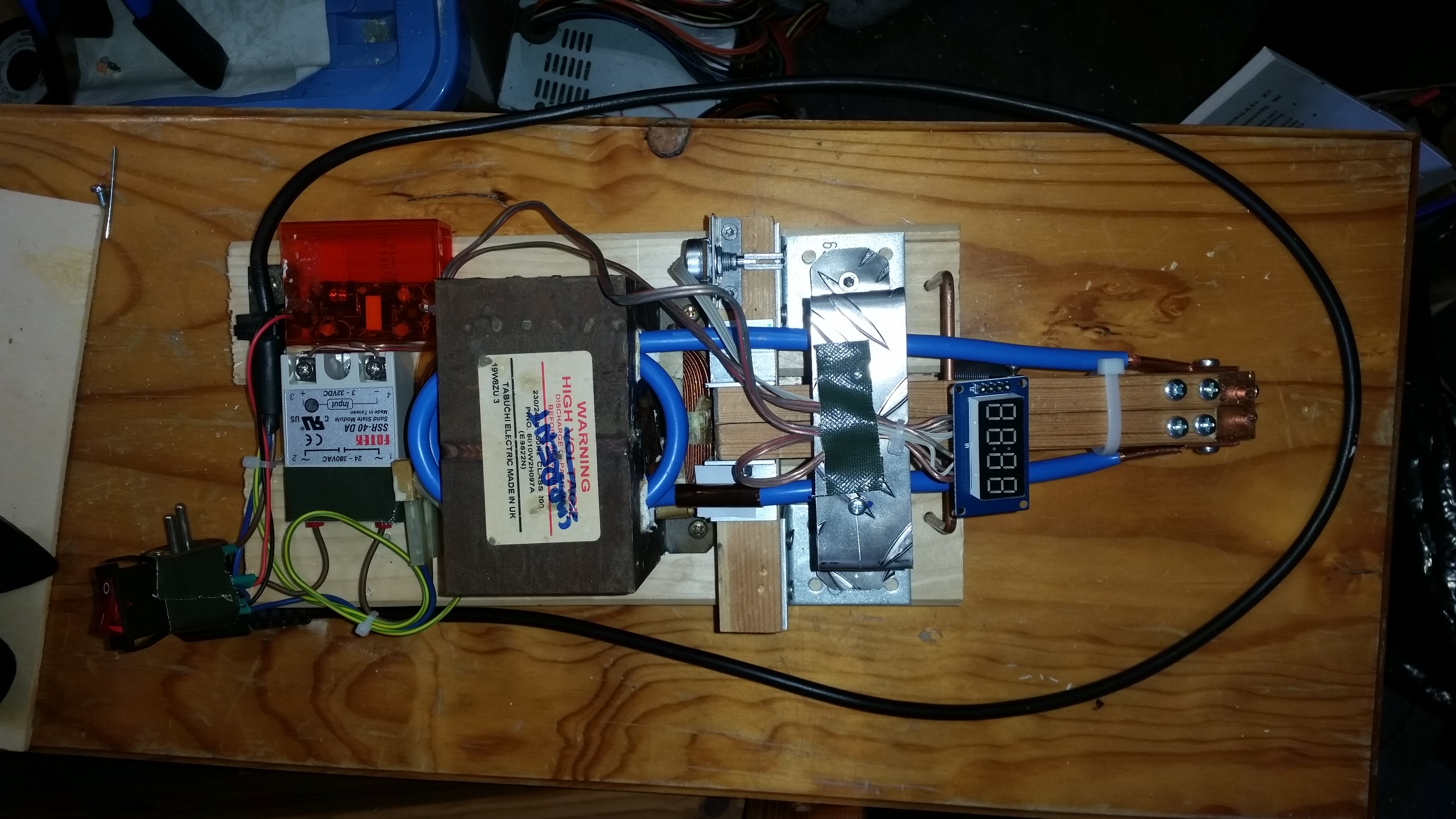
The device has been fixed on 8mm plywood for safe benchtop testing. Also, a couple of videos have been recorded.


Every stage was upgraded with 340µF for a total of 400J! The improvement was not as good as I thought, but as soon as the chronograph is ready, some precise measurements have to be performed. Charge time is less than 10 seconds.


20121013_183115


Now some more results:


Exit hole:


20121014_130314


Update:


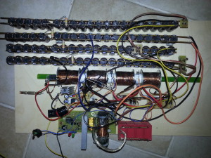
Ok, since I had many spare capacitors and stuff for the photodetector circuits, I decided to add (yeah, right!) 3 more stages!! Upscaling is not a big deal if you keep following an approved concept.


The 5th – 7th stage were supposed to have coils with greater wire gauge (1.8mm) for further decreasing Ohm’s resistance and allowing for greater currents. Besides that a slightly different coil concept was followed in the “second half” of the coilgun: I decided to have fewer and fewer layers but increasing coil lengths to have the acceleration path increase and the pulse duration decrease to account for the fast accelerating projectile.


After the fifth stage I ran out of 2N6509 SCRs and used BT145 – 800Rs in stacks of three. They are rated for 300A surge current each, which is almost one kA per stage.


The fifth and seventh stage got me into some turbulences while testing the whole setup. The fifth coil shorted on two points on the steel washer, because the insulation layer got damaged there. This bug could be corrected easily though, removing the washer and using more epoxy.


20121120_213026


The seventh stage burnt the protected diodes (and some SCRs :() since i ran out of good ol’ UF5408 and had to use different ones. When the parts are replaced, the otherwise completed seventh stage will also work. Edit: since the protection diodes kept burning, I decided to use a smaller 50J bank with only 10 68µF caps and copletely leave the diodes. With a properly sized power dissipation resistor the smaller bank reaches its 400V when its bigger bros are done.


I think this device will not have more stages, because it is dedicated for portable use some day and therefore any more increase in in size is kind of making it inpractical.


20121225_191531


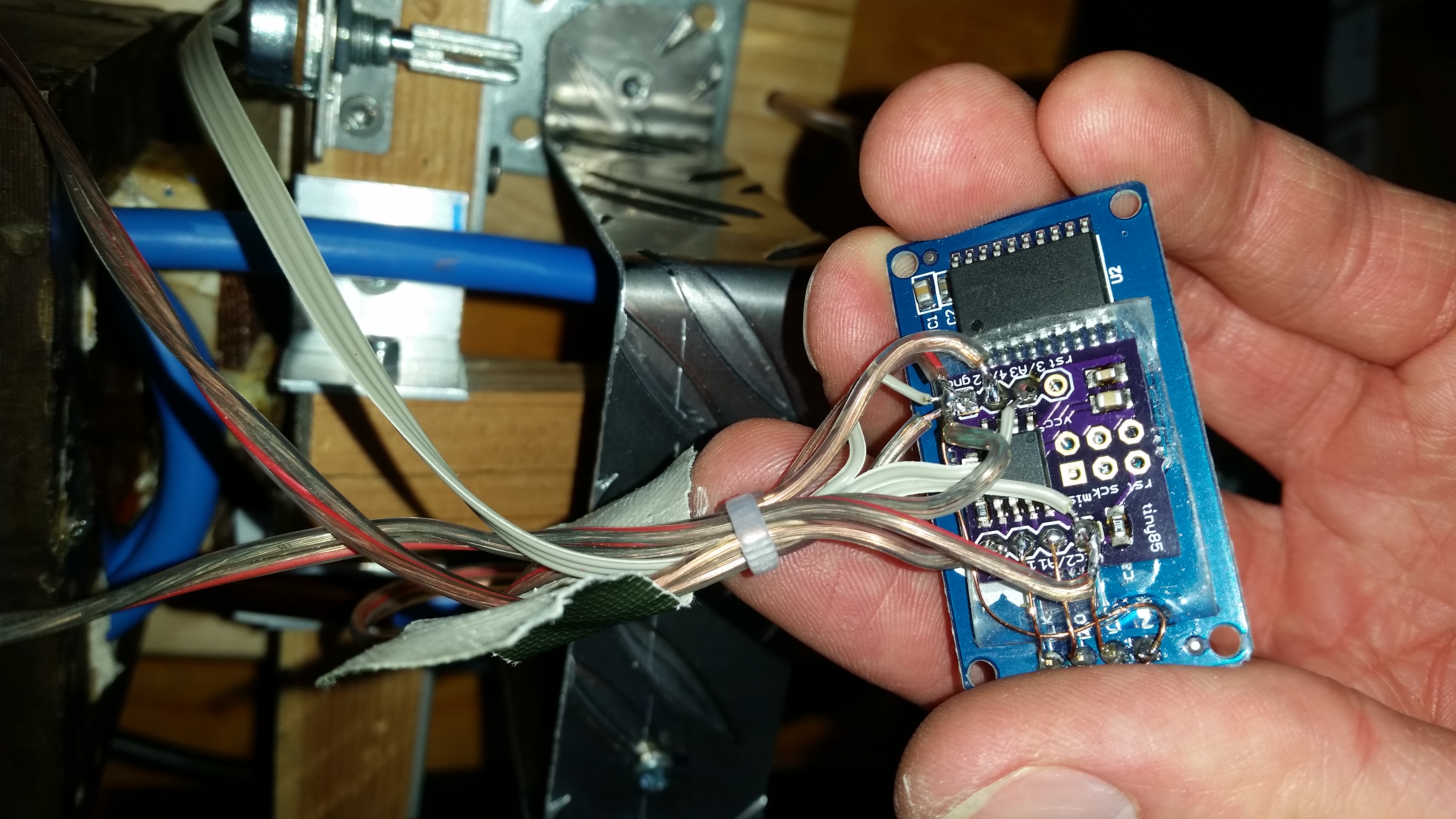
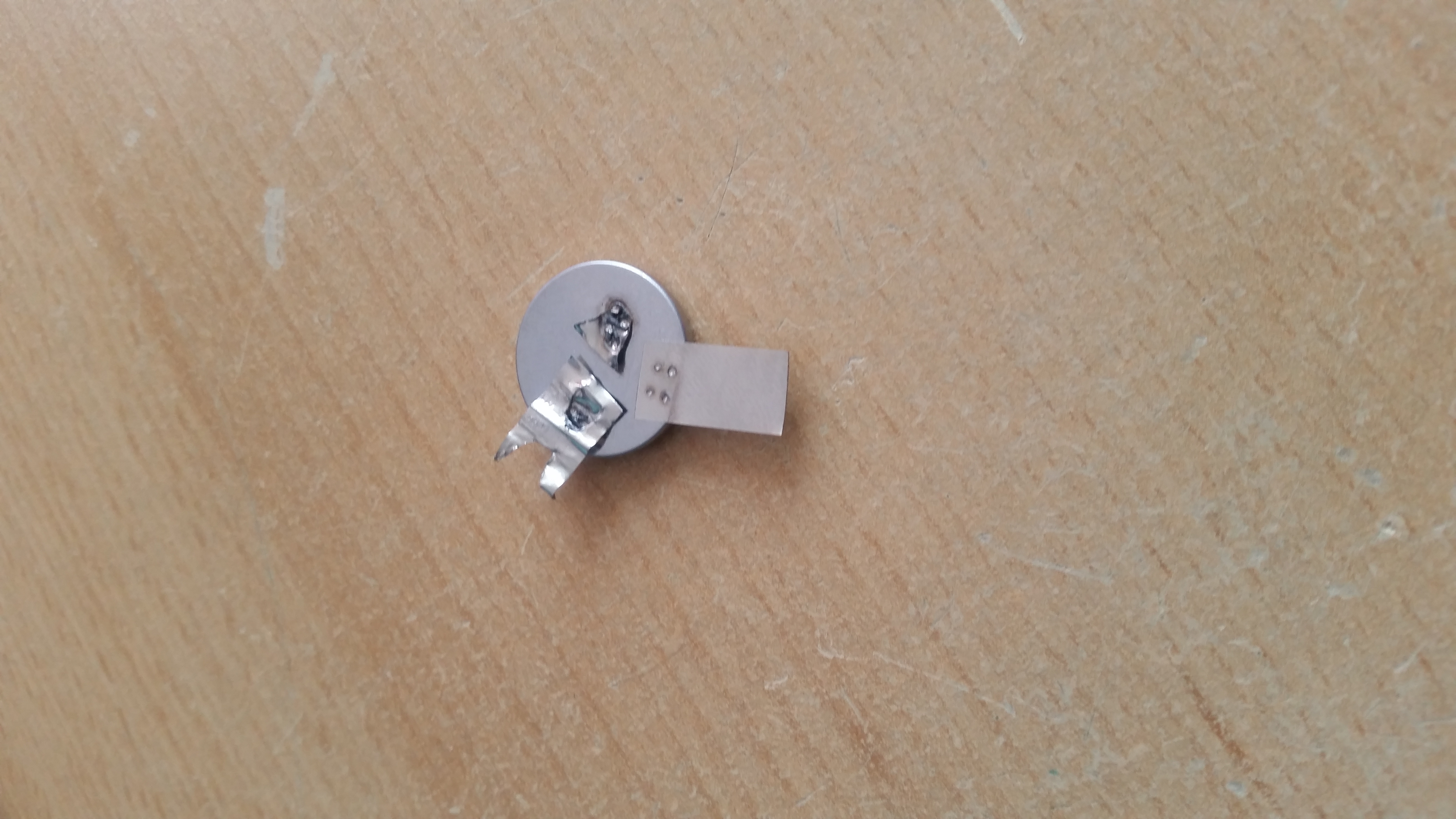
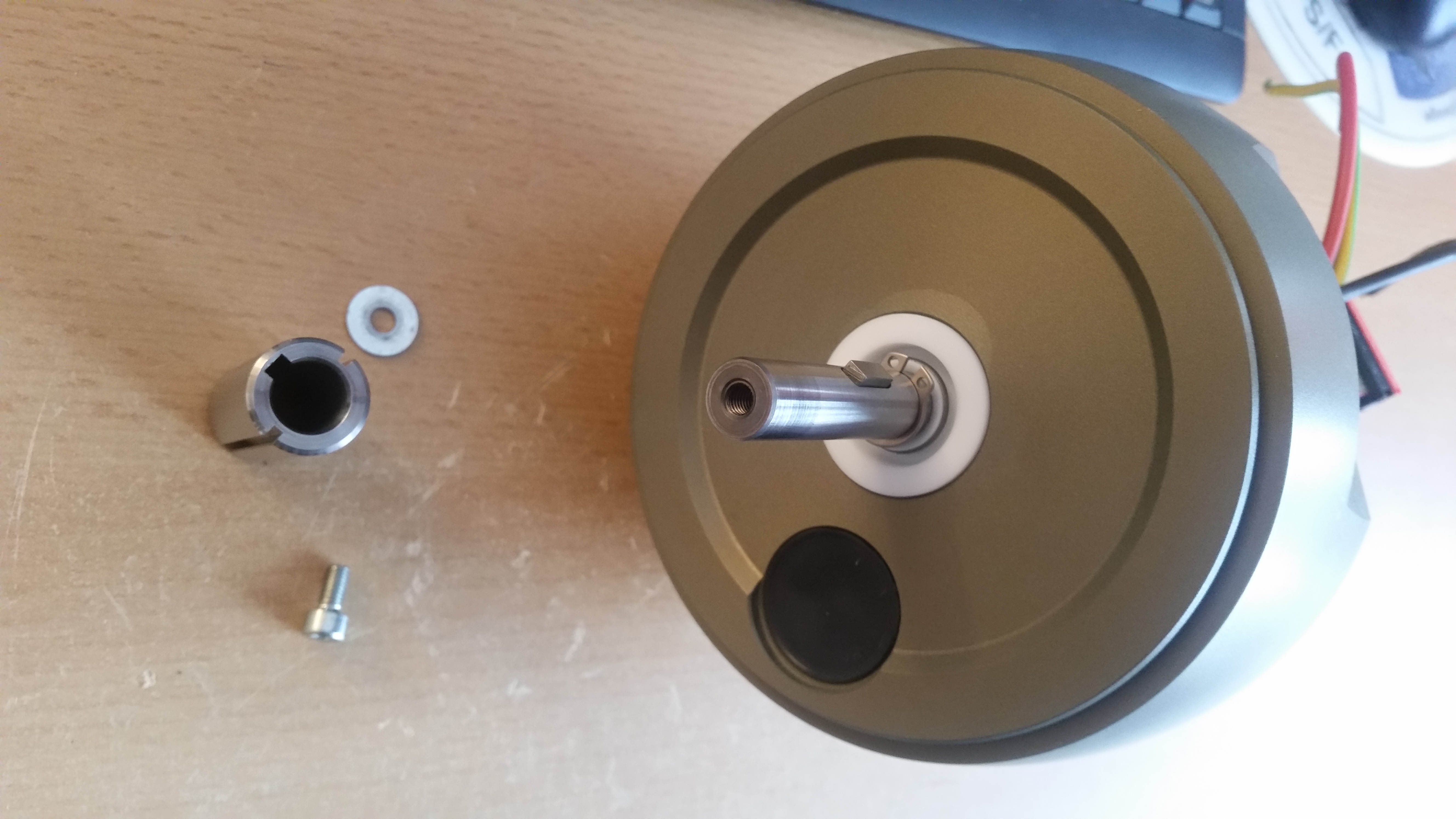
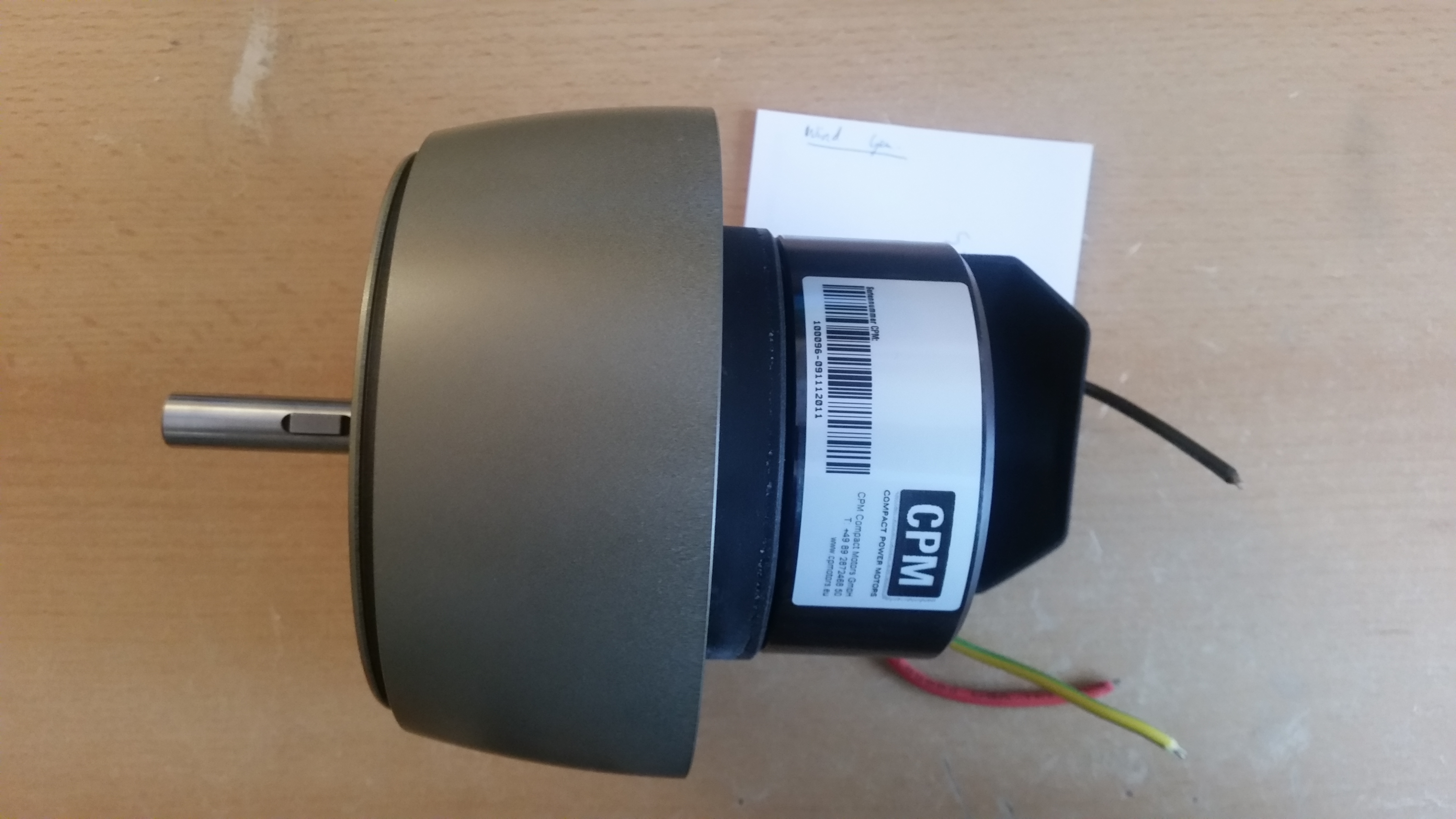
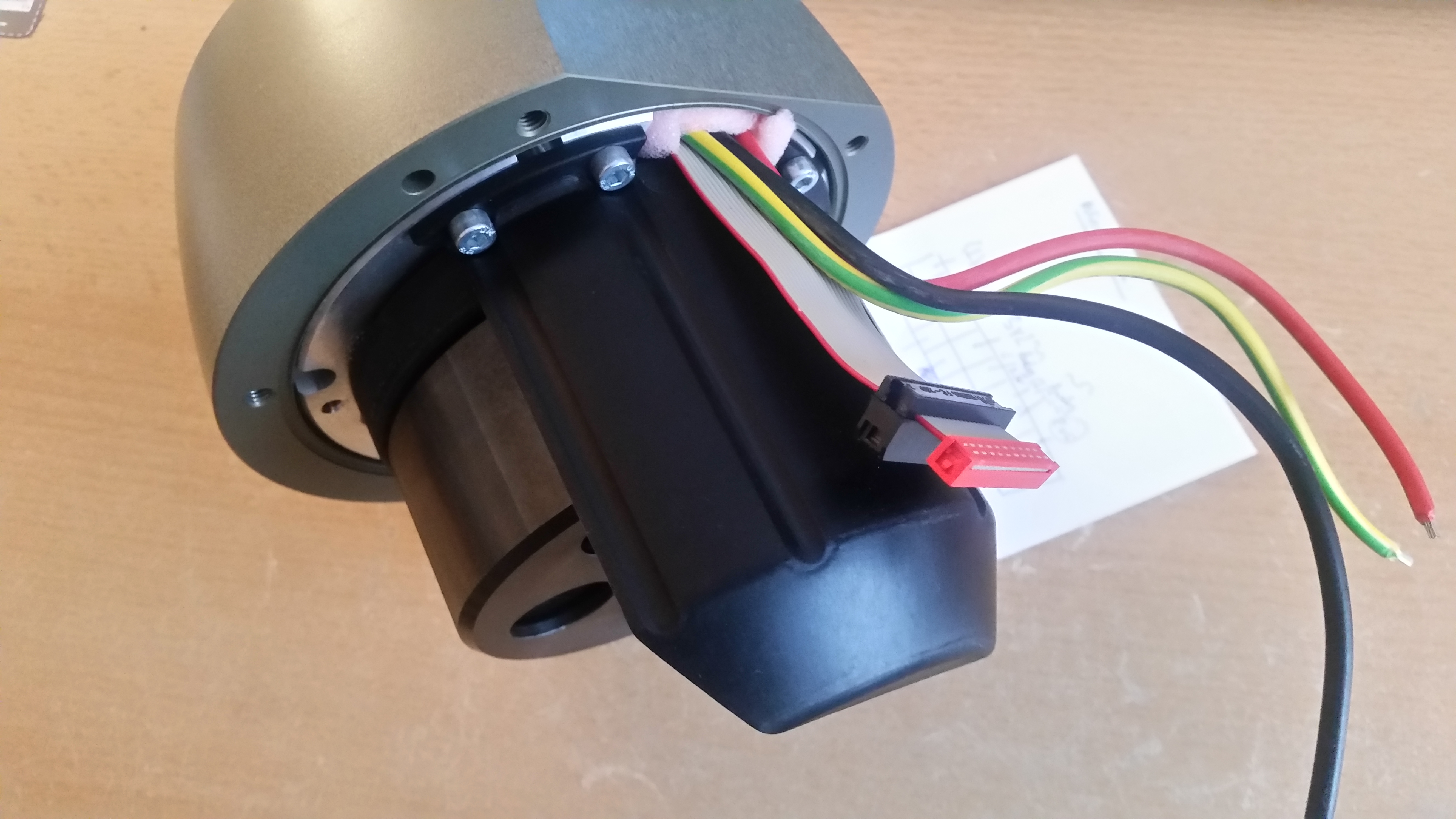
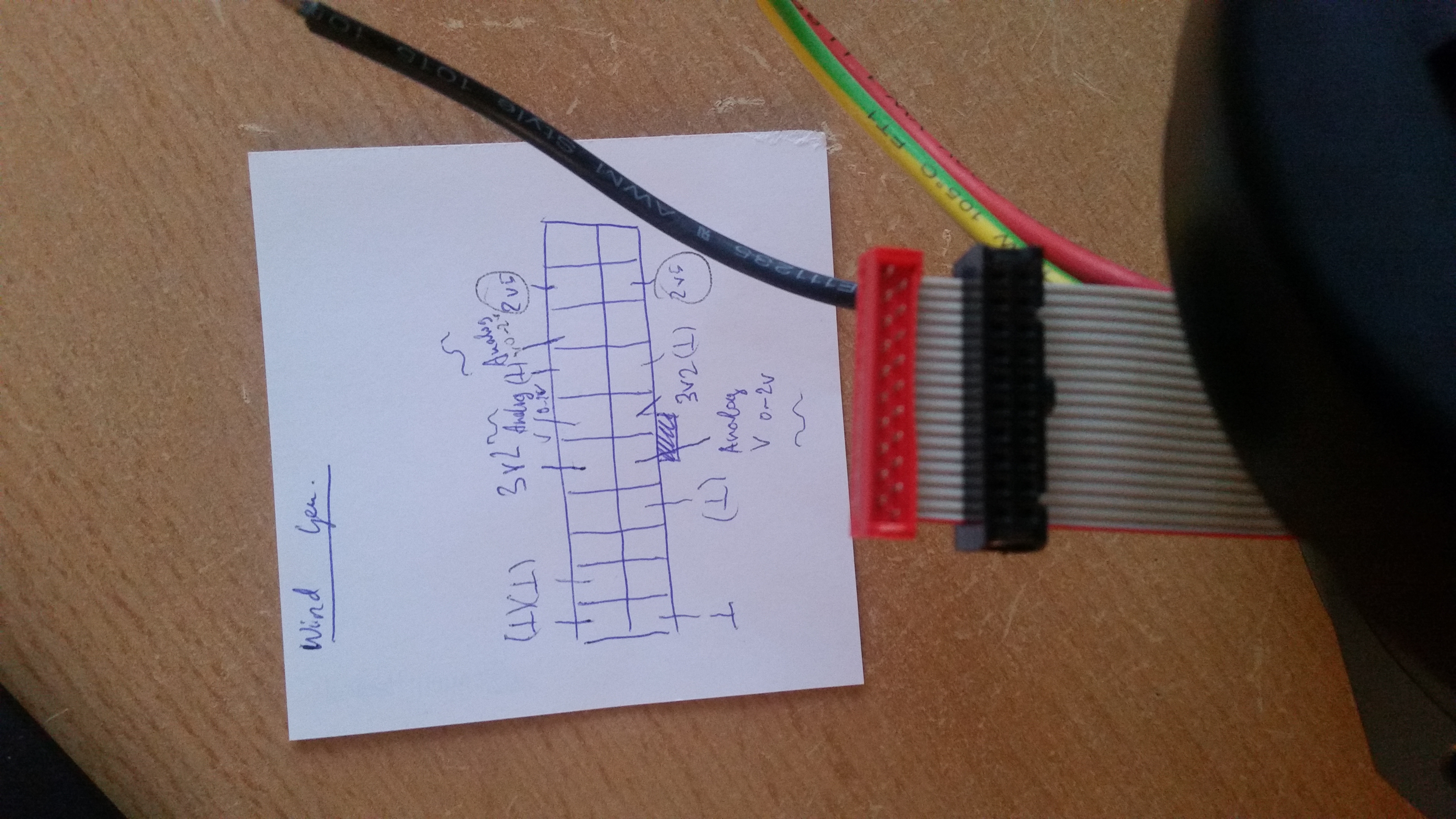
An idea that came to my mind is simply usind a DC motor with a small neodymium magnet for projectile rotation which is supposed to stabilize its trajectory. I’ve added PWM speed control to it so that it doesn’t spin too fast to stick to the projectile. Whether or not the trajectory of the bullet is affected by this concept remains to be tested over longer firing distances of, say, 10m.


20121124_180857


A video of 6 stages in action (projectile = 8 nails!):


Update:


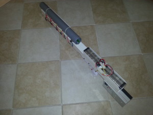
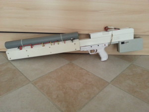
The guts have been built int an enclosure, finally. It consists of PVC for the most part and is held together using Tangit, which is an adhesive that welds this kind of plastic together. Only the casing of the charging circuitry is made of ABS, which sticks to PVC using the same glue though. Well, and the enclosure of the acceleration unit is a PP pipe which had to be screwed to the remainder as it is not affected by the solvent of the glue at all.


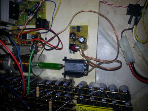
These are the final banks that will be used:


20121227_182351


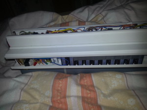
Below you can see the standard polypropylene pipe that will house the coils and light traps. The coils have been wrapped with sheet iron. Some authors claim improvement of performance. The diode bridge rectifiers and switching circuits will be built into a 40mm wide PVC cable enclosure at the bottom of the device.


20121227_182233


The cap banks for the first 6 stages are hidden in the double compartment shaft, the triggers and rectifiers are mounted below. The grip is a Nintendo Wii gun shaft for the Wii remote. It seems to be derived from the Walther P99 and is just incredibly ergonomic. It was just slightly trimmed, equipped with a reset switch from a computer and screwed to 2 massive PVC brackets that have been glue-welded to the PVC main shaft and we’re done.


20130310_221457


The cap bank, trigger circuit, rectifier and power dissipation resistor have been built into another piece of PVC cable enclosur and mounted to the side, since I didn’t want the finished device to exceed 1 meter in length.


20130315_111018


The battery housing was formed from the remainder of PVC profile that I had. The battery packs are held in place with Velcro strips.


20130315_110807


570J 7-stage coilgun rifle 400V


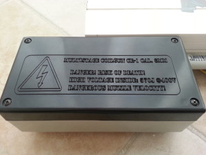
And of course, some words on safety precautions are appropriate, especially if one owns a DIY laser-engraving CNC machine 😉


gravurCG


Final specs:


the first 6 stages have capacitor banks with 16 caps à 68µF which store 87 Joule each when charged to 400V. The seventh stage’s capacitance is only 680µF which makes 50J @ 400V. Some power is dissipated through a 6k 5W resistor to make sure that after the same amount of time all stages have the same voltage. The overall stored electrical energy for all 7 stages is 572J. Charge time at 14.4V is below 10s.


A big screwdriver bit weighs almost exactly 10g. With a calibrated ballistic chrono a velocity of 50m/s was determined which results in a muzzle energy of 12.5J.


So overall efficiency is 2.1%

Tesla Coil

Tesla coil


I’ve built this mall ZVS-Driven Spark Gap Tesla Coil some years ago. It has got a simple dual spark gap, a MMC (multi mini cap) with a total capacitance of 2,27nF. The secondary coil has got 1065 turns of 0,2mm enamelled copper wire and a diameter of 21mm.


The primary coil is adjustible with a crocodile clamp.


The flyback transformer is powered using the ZVS (zero voltage switching) technique. This driver is also known as the Mazzilli Driver….just google it and you’ll find out, in case you don’t know what this is about ;). It can push a flyback to its limits…I’ve never powered this lil’ thing above 50W though, I don’t know, maybe soon 😉


You get nice 10cm long streamers from this device when powered off a 3S LiPo battery.


Here’s the device at 22V (6S LiPo Battery):


Coilgun Pistol

50J Multistage Coilgun Pistol cal. 6mm – a project I made real 5 years ago. The construction process of this pistol is quite well-documented on photos. Enjoy….


Readytofire


Accelerator apart


Readily wound coils: the first one uses 0,8mm enamelled copper wire (forgotten how many turns it had, probably around 200) and has the biggest capacitor bank. The other 2 coils have thinner wire, but also more turns for a stronger magnetic field. For faster discharge and smaller dimensions their capacitor banks are smaller.


The TO220 Parts are SCRs (2N6509) for 250A surge current. The phototransistors with their IR-LEDs are also waiting to be built in. The circuit board contains single-transistor circuits for the optical projectile detection. A 7805 is also on board.


The gun has got 2 power supplies: a 9V battery for the control circuit and laser sight and AA batteries for charging the capacitors…


Acceleratorstage Top


Here we have the completed accelerator stage with optical projectile detection, coils and Thyristors.


CG Apart


This photo contains pretty much all parts as well as the schematic diagram. You can see where most of the capacitors are going to live. The 4 caps in parallel are all for the first stage. Right above them you see the tiny charging circuits. I’ve extracted them from three disposable cameras and re-soldered the most important parts (only the tiny transformer, one resistor and the transistor as well as the diode) on a piece of perfboard. Each stage has got its own charging circuit. Stage 1 and 2 are Kodak-derived and stage 3 is Fujifilm-derived. It takes about 40s to charge the caps to about 330V, depending on the AA batteries you use.


The handpiece is from an old airsoft gun by the way. The trigger switch is also built in already (taken from an old computer).


Inverter, Griff, Bank


A close-up to the charging circuitry with some more wiring accomplished. The LEDs and the neon bulb at the end of the wires are for charge detection. Kodak uses LEDs, Fujifilm those neon bulbs.


Gesamt-Auseinander


Tight, but it fits!


Gunmod 2


Some insulation was done, a red laser mounted and the bottom of the accelerator stage covered with aluminum sheets, which have been cut out of a spray can :).


A typical shot with a “stabilized” pointed projectile. You can see that it penetrates from larger distances.


Simply a big iron slug cal. 6mm.


An exact measurement of the muzzle velocity has to be done some day to determine efficiency, but it seems not bad at all. The thing even punches holes into tin.


Damage Metal

Mendocino Motor


A Mendocino Motor is an optically commutated, magnetically levitating, solar powered Rotor.
This one consists of 3,6mm plywood and was completely machined with my CNC mill. The Design has been accomlished in Google Sketchup, the G-Code was generated with the Phlatscript plugin.


mendocino base sketchup


mendocino rotor sketchup


20120801_191328


Mendocino


The dimensions can be estimated from the screenshots. After milling the parts are taken out of the plywood sheets (cut the tabs that hold them in place) and just pressed together, no glue necessary!
The 2 coils have ~100 turns each with 0,3mm enamelled copper wire. The solar cells are capable of delivering 200mA at 0,5V.
At the end of the rotor that has contact to the mirror a tip of a pencil has been inserted (see pic above) to minimize friction, due to the lubricating properties of graphite.


Sketchup files (1 for the base and 1 for the rotor):
SketchUp files