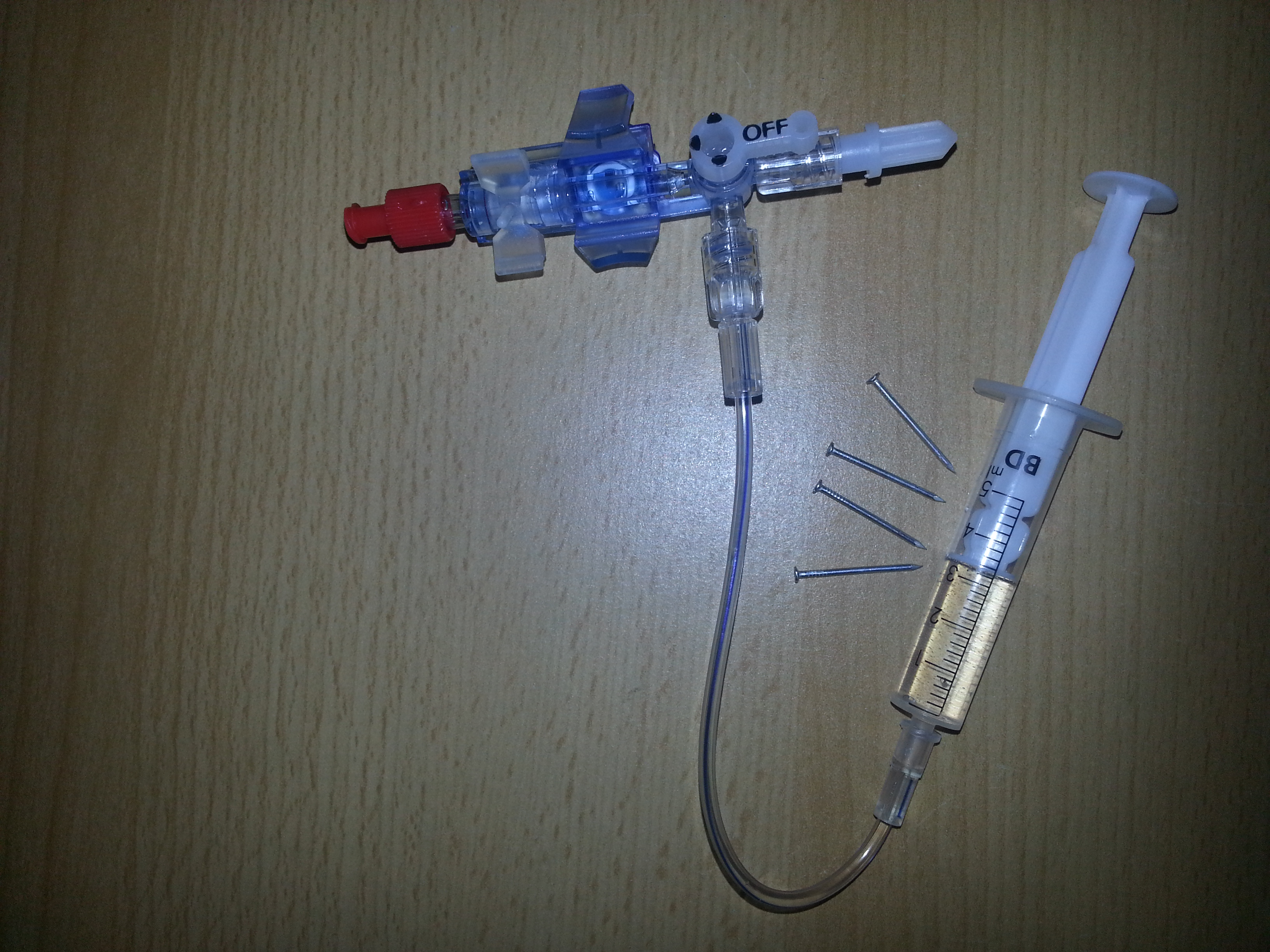
I’ve recently found a single-use medical grade pressure sensor, as used in invasive catheter blood pressure measurements in critical care medicine.
It has got 4 output terminals as you can see in the picture below where one can simply insert small 1mm nails…
The internal configuration seems to be a Wheatstone Bridge and therefore it has to deliver an analog output. So some measurements of the resistances between the terminals were made which quickly led to the following test setup:
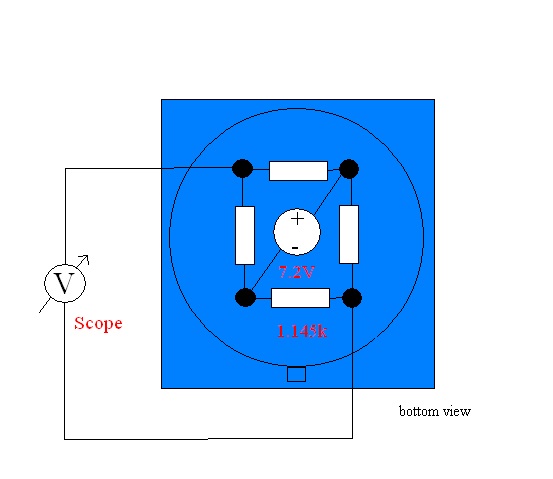
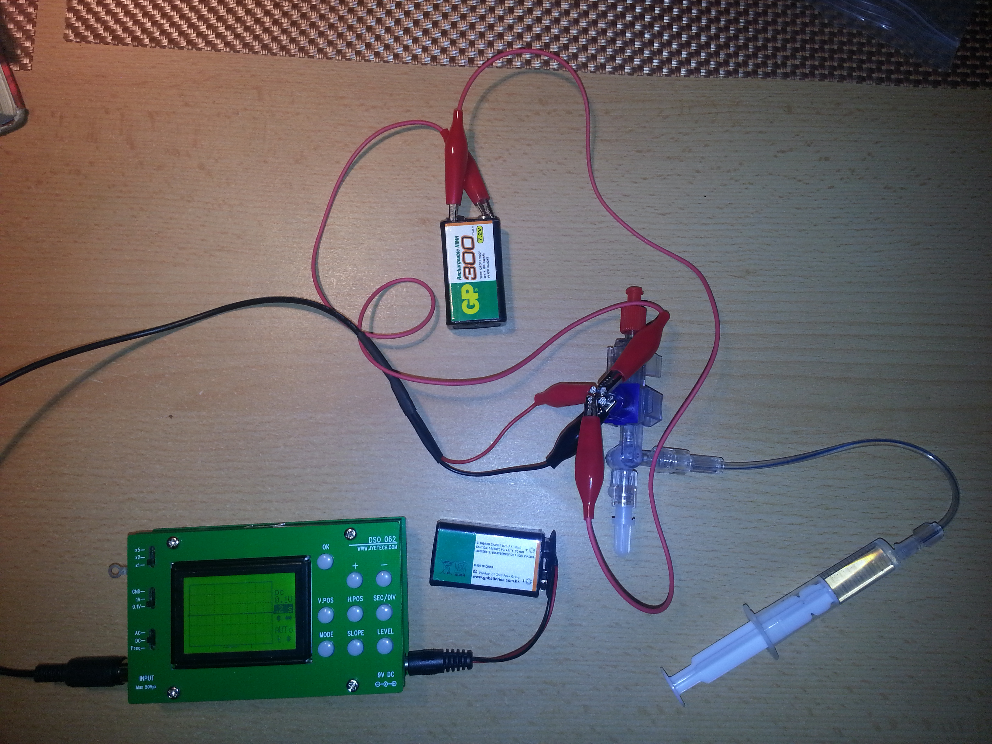
With 7.2V connected to the sensor the amplitude of the output voltage is at about 0.1V
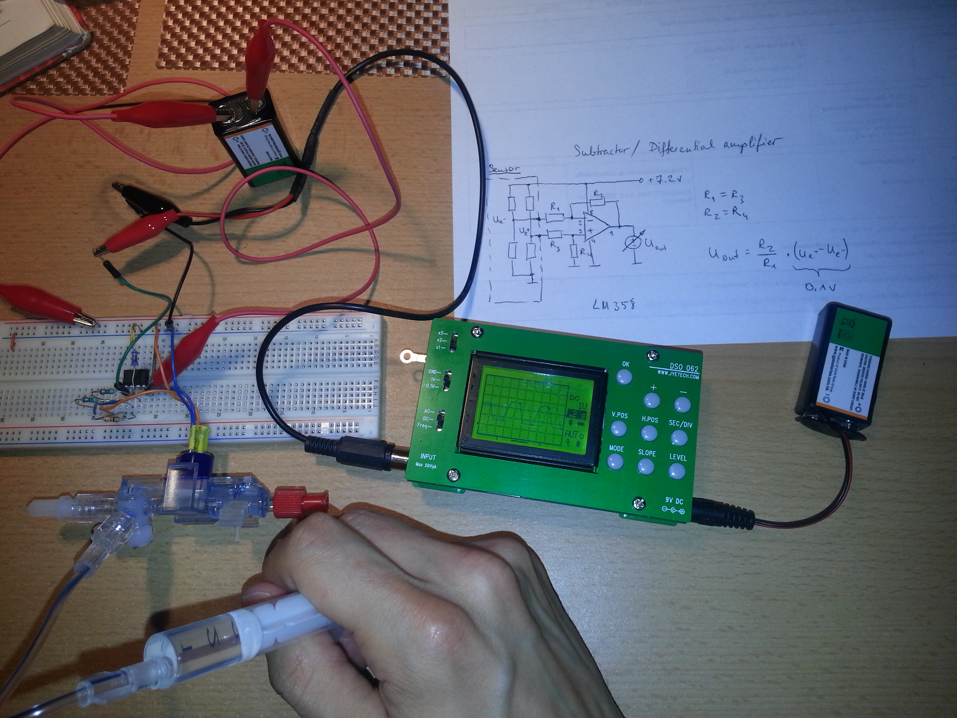
A simple opamp-based differential amplifier was used to amplify the output.
Hello,
thanks for sharing your hack.
I’m trying to read the data from the same kind of transducer (even if mine has 5 output wires).
I have a few questions:
– the amplificator you used is an LM358 ?
– what is the maximal pressure you can measure?
– what is the accuracy of the measurement ?
Thanks
Hi, yes I used an LM 358 but I haven’t figured out the pressure range of the sensor since I have nothing to compare it against. I think you should be able to verdrive it.
also how did you manage to determine on which wire you should apply the voltage and on which you should get the measurements ?
I measured the resistances between all terminal pairs and tried different wiring configurations until I got a pressure-dependant voltage response on the scope.