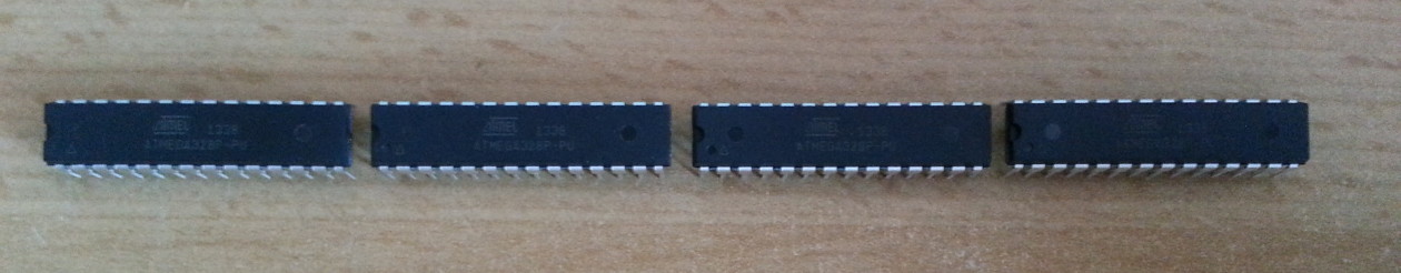
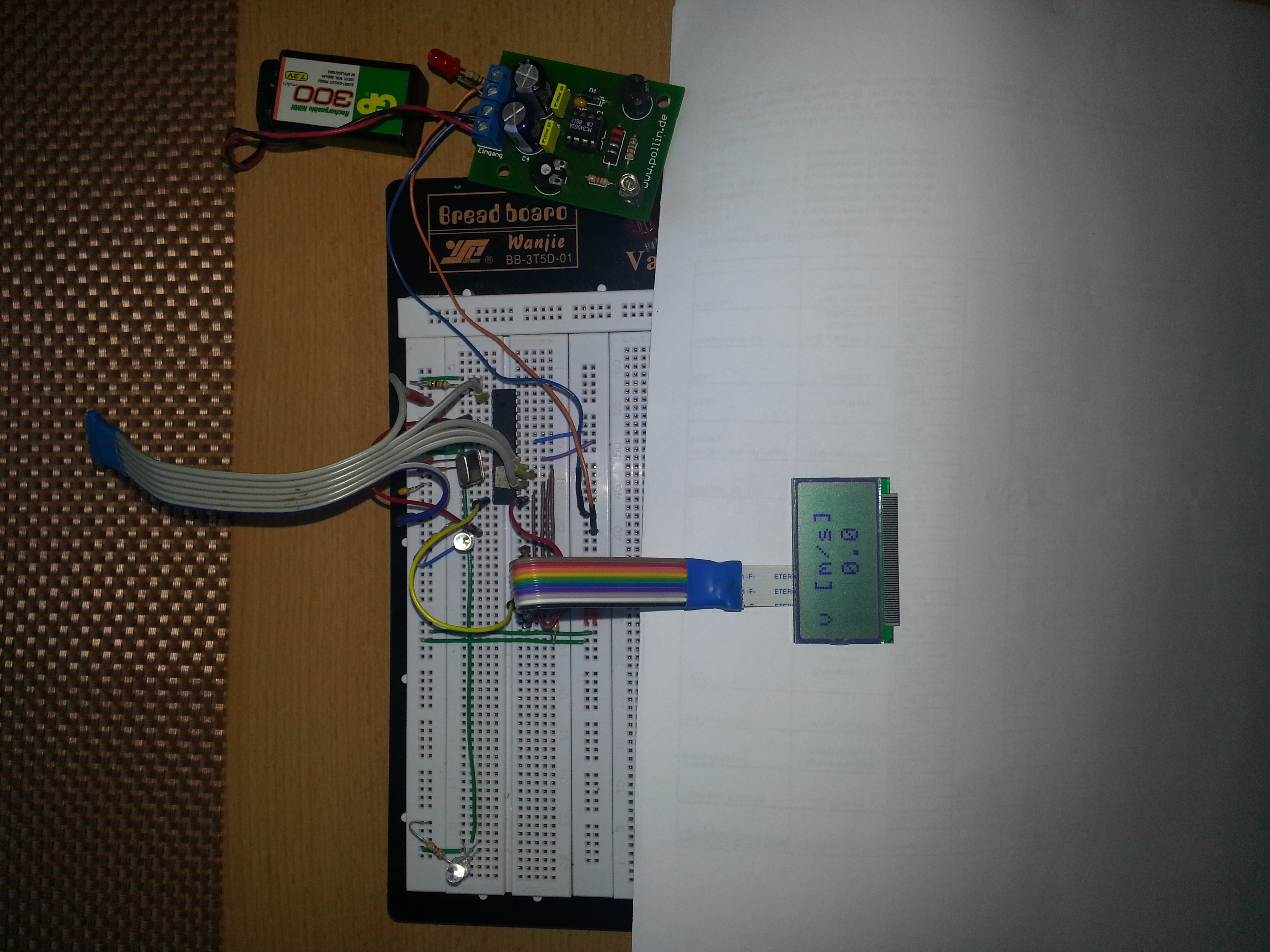
Projectile velocity meter based on the Atmega8. It’s still in the breadboard stage of development, but is working already. I’m going to use it to measure the velocities of the coilgun projectiles to determine muzzle energy and efficiency.
The Software was written in BASCOM basic, since this was the platform I started programming microcontrollers. The cheap 2×8 character LCD is connected to PORTB. The INT0 and INT1 pins have a BPW40 phototransistor (positioned 10cm apart from each other) and a 4.7K pullup-resistor connected to each of them.
As long as the light beam hits the phototransistor, it pulls the pin to ground. If the beam is broken, its resistance rises and we’ve got our rising edge on the interrupt pin. INT0 starts the Timer, INT0 stops it. A simple calculation is performed and we’ve got our velocity in [m/s].
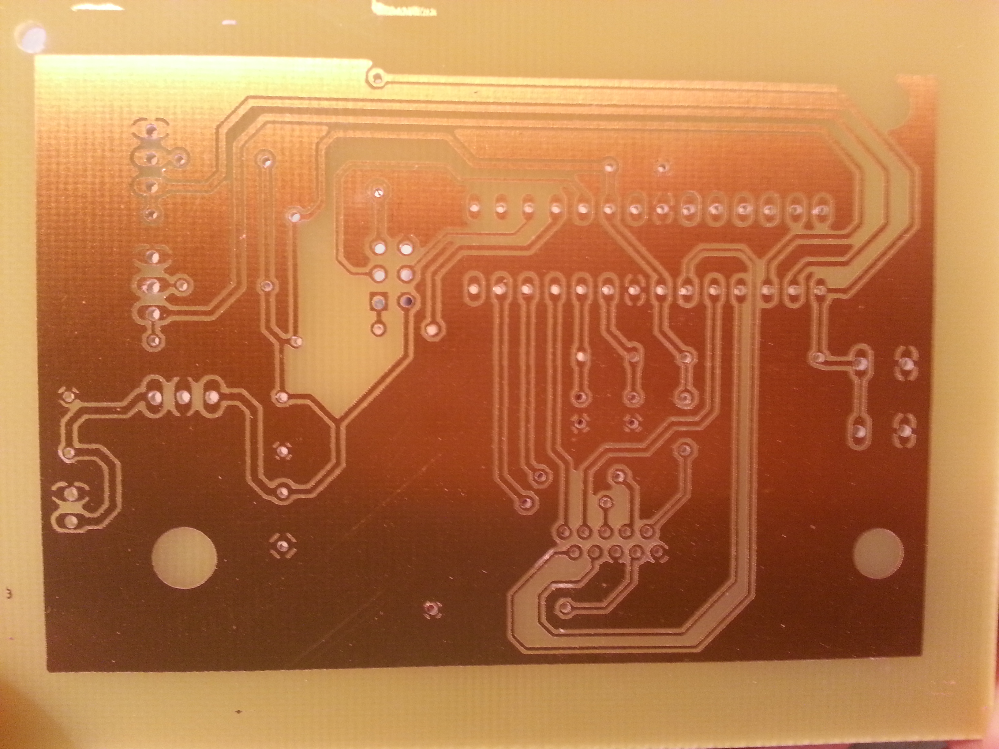
This side-project was taken as an opportunity to make a PCB with Eagle CAD and the photoresist method. I’ve been making my own PCBs at school, but that was some time ago.
Also, the code was completely rewritten in C using AVR Studio 4.
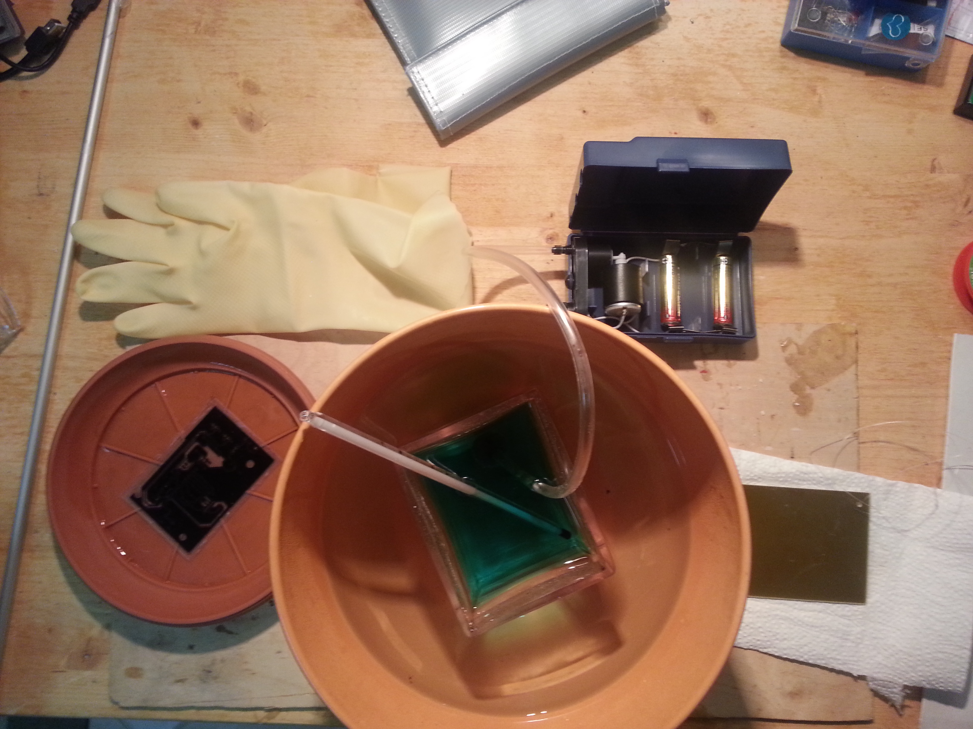
Below you see my experimental etching setup. A water bath heats up the sodium persulfate to up to 50°C and the aquarium air pump creates some bubbles for movement of the solution around the PCB.
The stencil for developing the PCB was printed on inkjet overhead projector transparencies. 3 stencils were printed and superposed to make the traces more solid. My conclusion is that you don’t reach a resolution high enough for SMD components, at least not with my printer.
The final result: The finest component is the ribbon cable connestor for the LCD, a custom eagle part was created for it.
The brackets for the light barriers were milled using a Proxxon BFB2000-SI-BFW 40/E-SI-KT 150 setup. The IR LEDs and photodiodes were scavenged from some old device.
The final PCB: coated and soldered.
The final assembly: the light barriers are 30cm apart.
Despite having learned a lot during developing this machine, I would consier the end result to be a typical maker FAIL, since this is a very inaccurate instrument. I should find out why this is so some day. Whether it is the source code or the physical assembly…
But I don’t regret a thing! It was a great motivation to acquire some very useful skills!
The Code, as well as the eagle files are found under the link below.
Chronograph