DIY CNC Machine
This is a CNC Machine I’ve built. It is capable of milling using a 100W 230VAC proxxon handheld multitool and laser engraving/cutting with a 1W 445nm diode laser. It mainly consists of parts from the hardware store and is actually low budget.
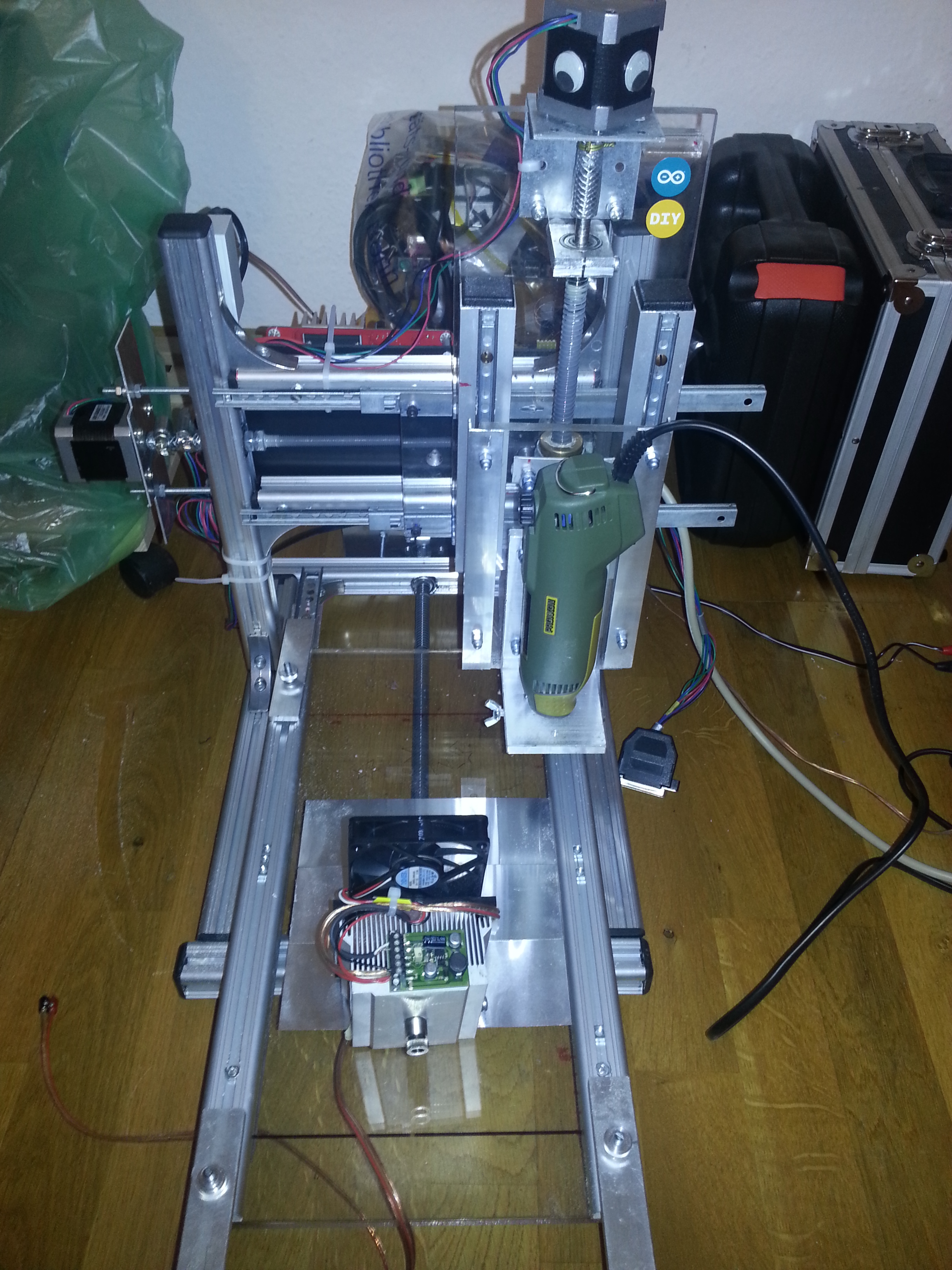
Front side with the milling tool in place and the 445nm 1W laser diode in an AixiZ module with its 800mA constant current regulator, CPU heatsink and fan for smoke removal.
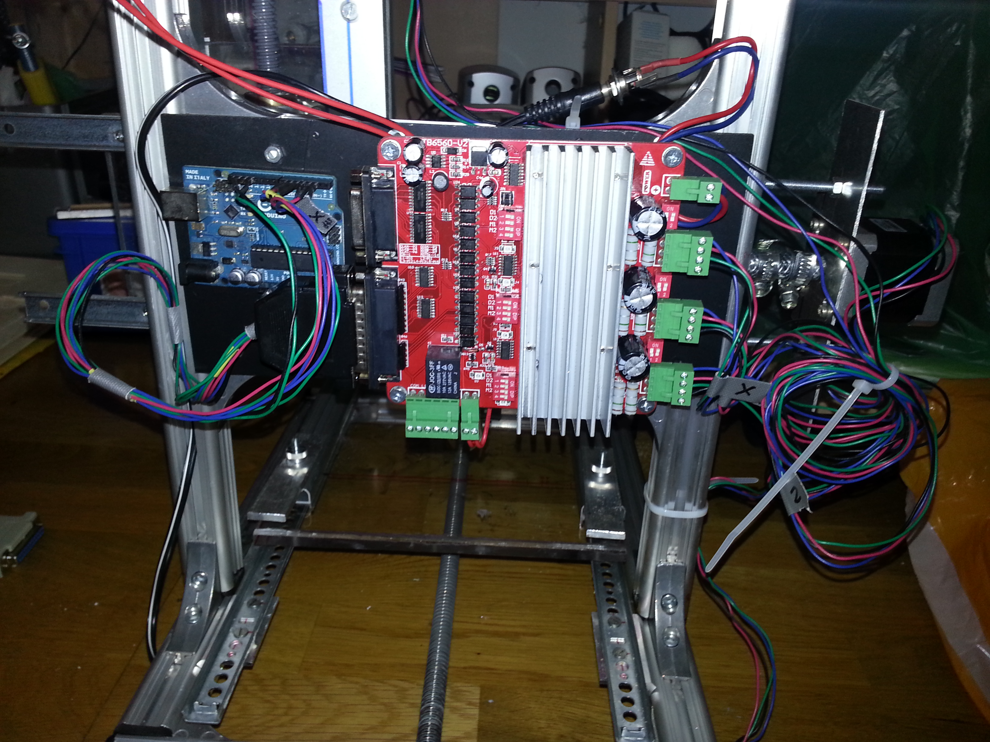
The steppers (NEMA17, 1,6A) are driven by a TB6560-based 3Axis control board rated for up to 3A.
Our local hardware store around here had those awesome aluminum profiles, which are affordable, as well as easy to use. They make a very precise and stiff frame.
Exery axis works with standard drawer slides. Given the fact that they make dirt-cheap linear motion guides, the result is quite satisfying. There is, however, some play in the Z-axis when it’s fully moved out. When working with materials such as plywood, this doesn’t impair the precision, which is still in 1/10mm area. The overall working dimensions of the setup are 19cm in the X-axis, 30cm in the Y-axis and >8cm in the Z-axis, which is enough for DIN A4-sized materials.
The X-Axis uses a standard stainless M8 threaded rod with a long steel nut (never change a winning team ![]() ), whereas the Y and Z-Axes have been upgraded to 12mm Acme-Rods with 3mm pitch. The couplings are good ol’ Gardena garden hose tightened with hose clamps.
), whereas the Y and Z-Axes have been upgraded to 12mm Acme-Rods with 3mm pitch. The couplings are good ol’ Gardena garden hose tightened with hose clamps.
I’m using 2 different software plattforms, depending on what has to be done:
- over the parallel port: Google SketchUp with the Phlatscript plugin and LinuxCNC for milling
- over the GRBL G-code interpreter on an Arduino via USB: Inkscape with the laser engraver plugin and GcodeSender for laser engraving/cutting. A great description of this extremely useful toolchain can be found here: http://www.instructables.com/id/Pocket-laser-engraver/step7/Getting-the-software-ready
If the laser has to be used it has to be pluged into the red and black female jacks below the power supply jack (grey box on one of the columns). Otherwise they are used for the M03/05 command for switching the milling tool (see lower picture).
Some words on the development process
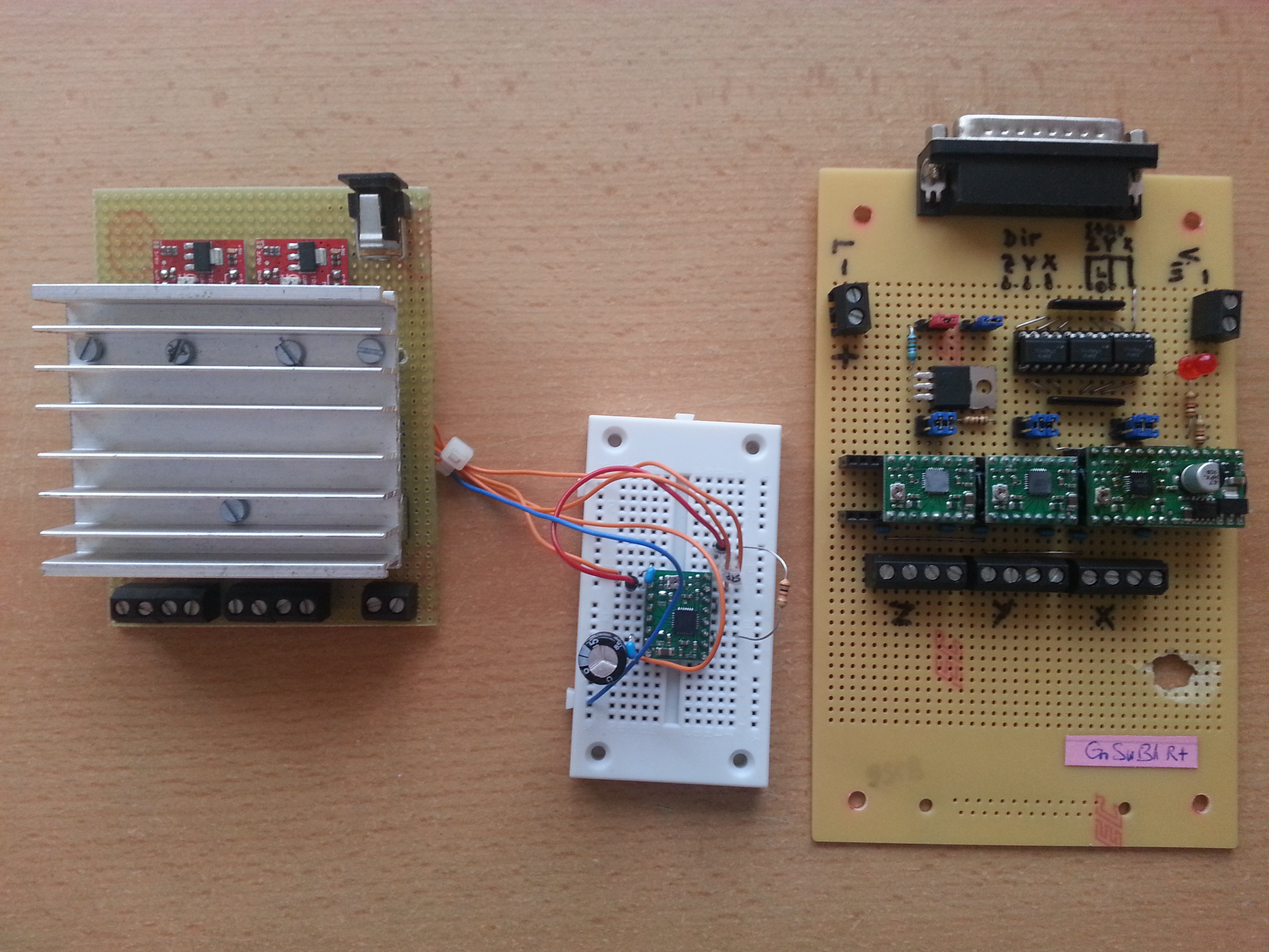
I’ve built 2 versions of driver boards for different purposes before. On the left of the picture below you can see an arduino “Laser Shield” based on 2 Easy Drivers (http://schmalzhaus.com/EasyDriver/) and a FET for switching the laser. Since te chips became very hot, I gave them a good heat sink. Some wires have been added to be able to have a Pololu driver control the Z-axis on a milling setup. The A3967 can deliver a maximum of 750mA per phase which was not quite sufficient for a milling setup, so I had to think further.
On the right you can see my optocoupler-isolated parallel port board for Pololu (A49xx) carrier boards. These drivers can deliver 2A per phase (with proper heat dissipation) which was better. A FET for laser control is also on board. For some reason The chip for the X-axis died (it sits on the carrier with the voltage regulator). I sampled some A4988 and replaced it twice, but that kept happening. That drove me nuts, so I decided to try a TB6560 based board.
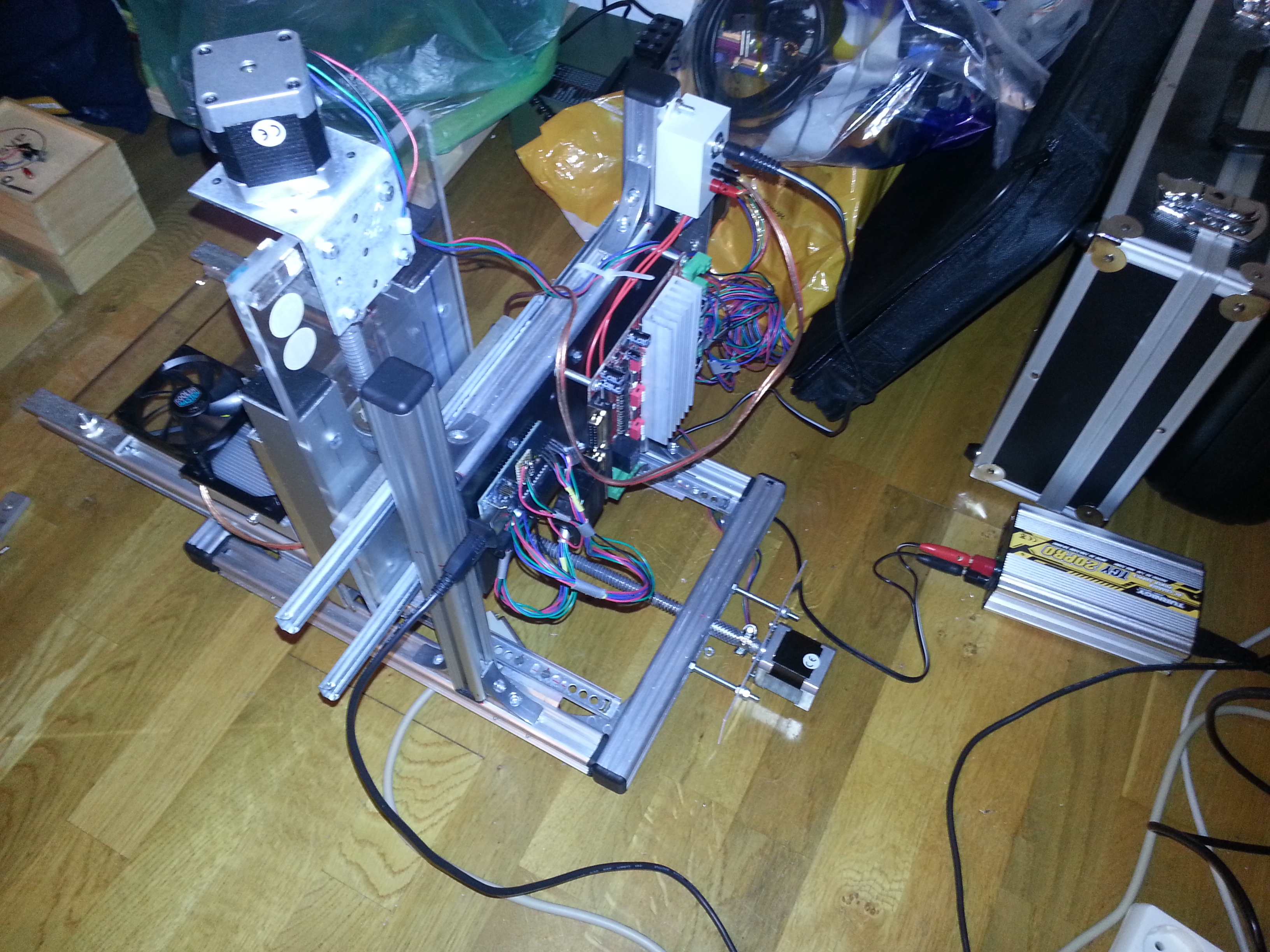
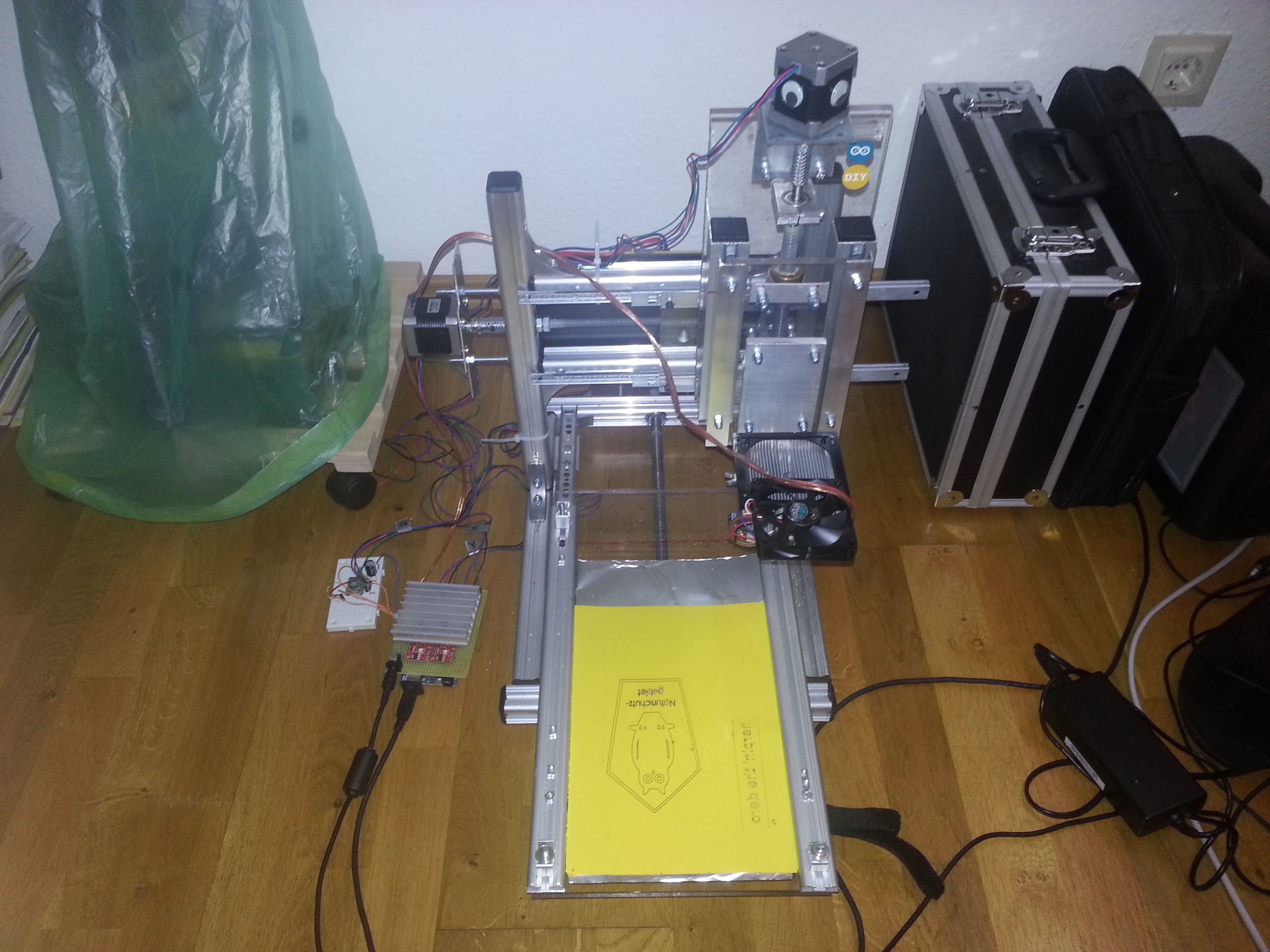
Here you can see the setup with the laser shield and the result on yellow paper. The board from ebay is by now also capable of driving the laser, so this is actually obsolete, but nice anyway 😉
dear builder!
thank you for your article, i love it.
but it isnt clear how did you connect the arduino to lpt (parallel) port? can you draw me, please?
Thank you
Hey, connection depends on the version of GRBL interpreter and CNC control software. Take a look at the GRBL source code https://github.com/grbl/grbl/blob/master/grbl/cpu_map/cpu_map_atmega328p.h there the DIR and STEP pins are listed. And as for LinuxCNC, Mach3 or whatever you’re using – you have to set it yourself anyway. There’s a ton of info online 😉