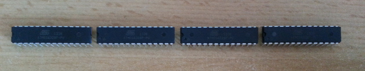
When working with RF modules that transmit/receive in the 2.4GHz or whatever range it’s sometimes useful to have some means to detect whether transmission really takes place. This wideband RF detector based on the LT5534 by Linear Technology is capable of doing so. Moreover it can tell, how strong the signal is, since its output ranges from 0V to VCC (5V in this case) and is proportional do the dBm of the received signal. The chip can be for free, which is what I did. The idea for this project as well as the first carrier board design was originally from Laboratory for Experimental Computer Science
at the Academy of Media Arts Cologne.
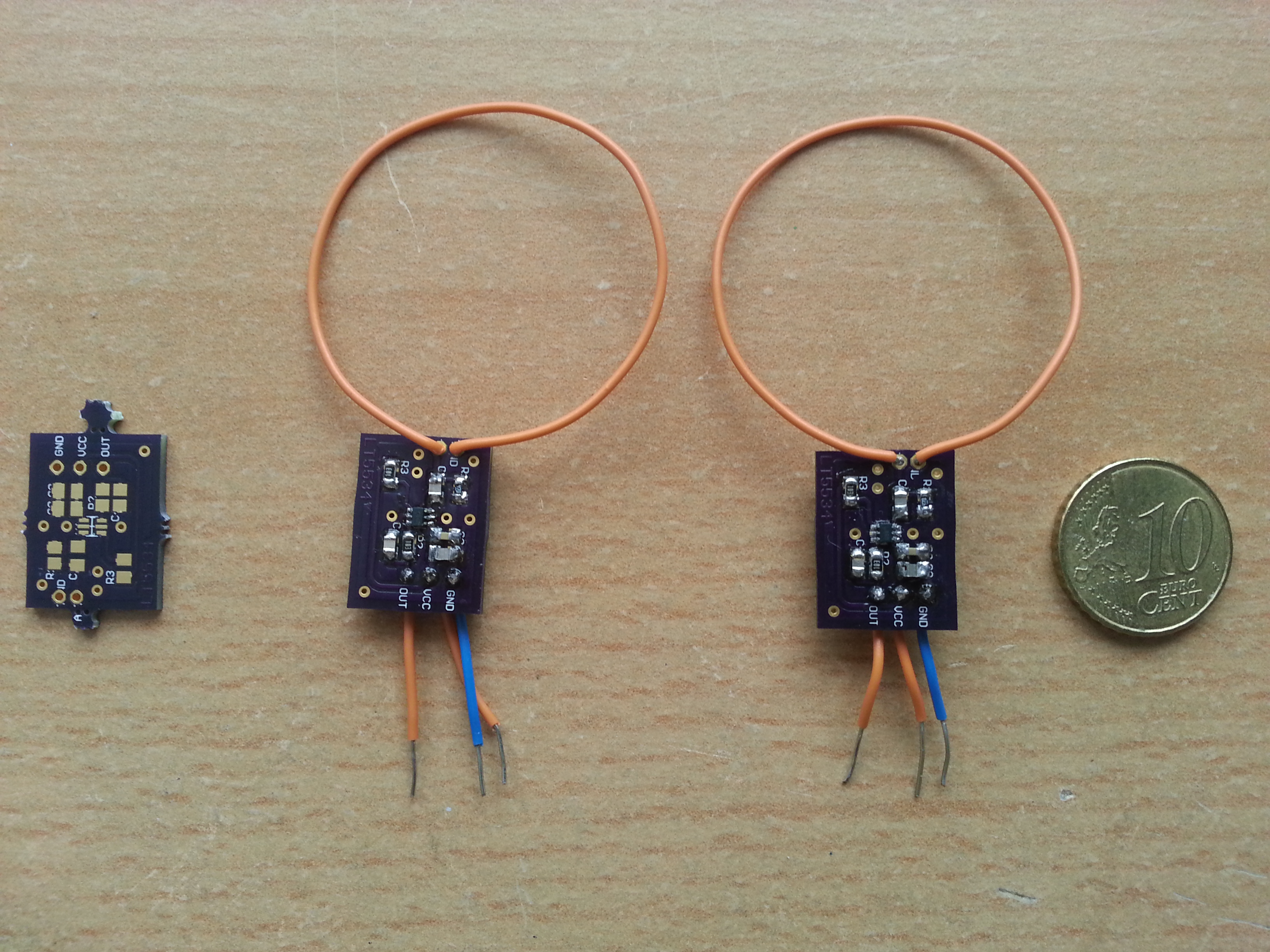
I improved the board a little and ordered some PCBs from OSH Park It takes about 2 weeks for them to arrive in Germany and costs almost nothing, since the boards, like the chip itself are tiny. Apart from the LT5534 itself the carrier board uses few standard components.
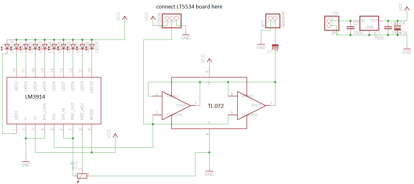
To have an audiovisual output I decided to add a LM3914-based bar graph meter and a speaker with a TL072 opamp buffer, since I had both of them lying around luckily. I added the buffer because the LT5534’s output cannot deliver enough current to drive the speaker’s membrane adequately. What you hear is the raw modulation of the incoming RF signals. It’s like getting a 6th sense for the invisible RF pollution around you. For example if you hear periodic knocking sounds, it’s probably from a WiFi router.
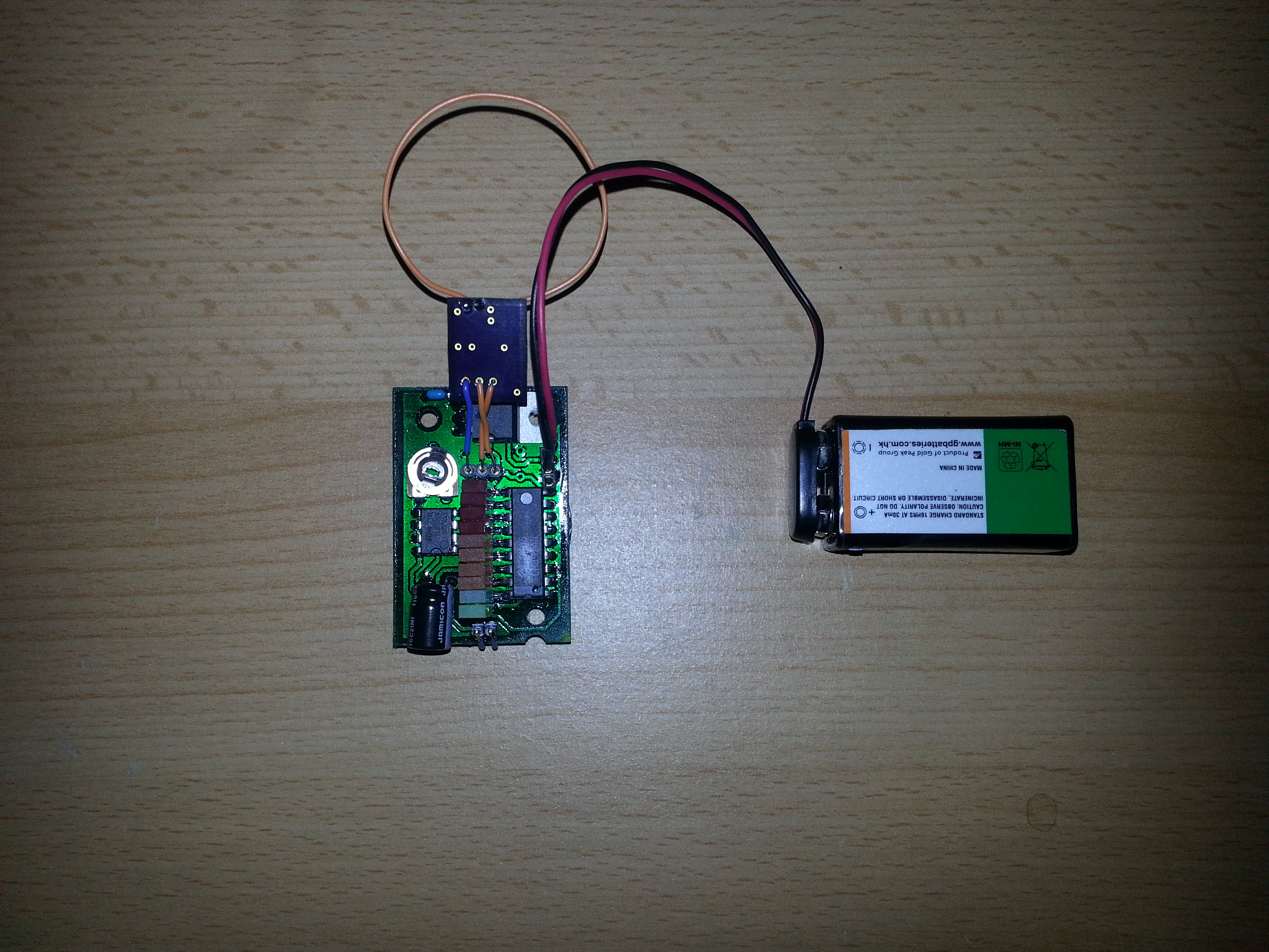
Here’s the preliminary breadboard version of the ciruit. The loop antenna was made for 2.4GHz but the device still receives signals over a pretty wide RF band. The PCB was designed specifically for the depicted enclosure. The carrier board will be connected to the bar graph board. The loop antenna will be replaced with a SMA jack with a coax cable pigtail to have the possibility to connect different antennas for different frequency ranges.
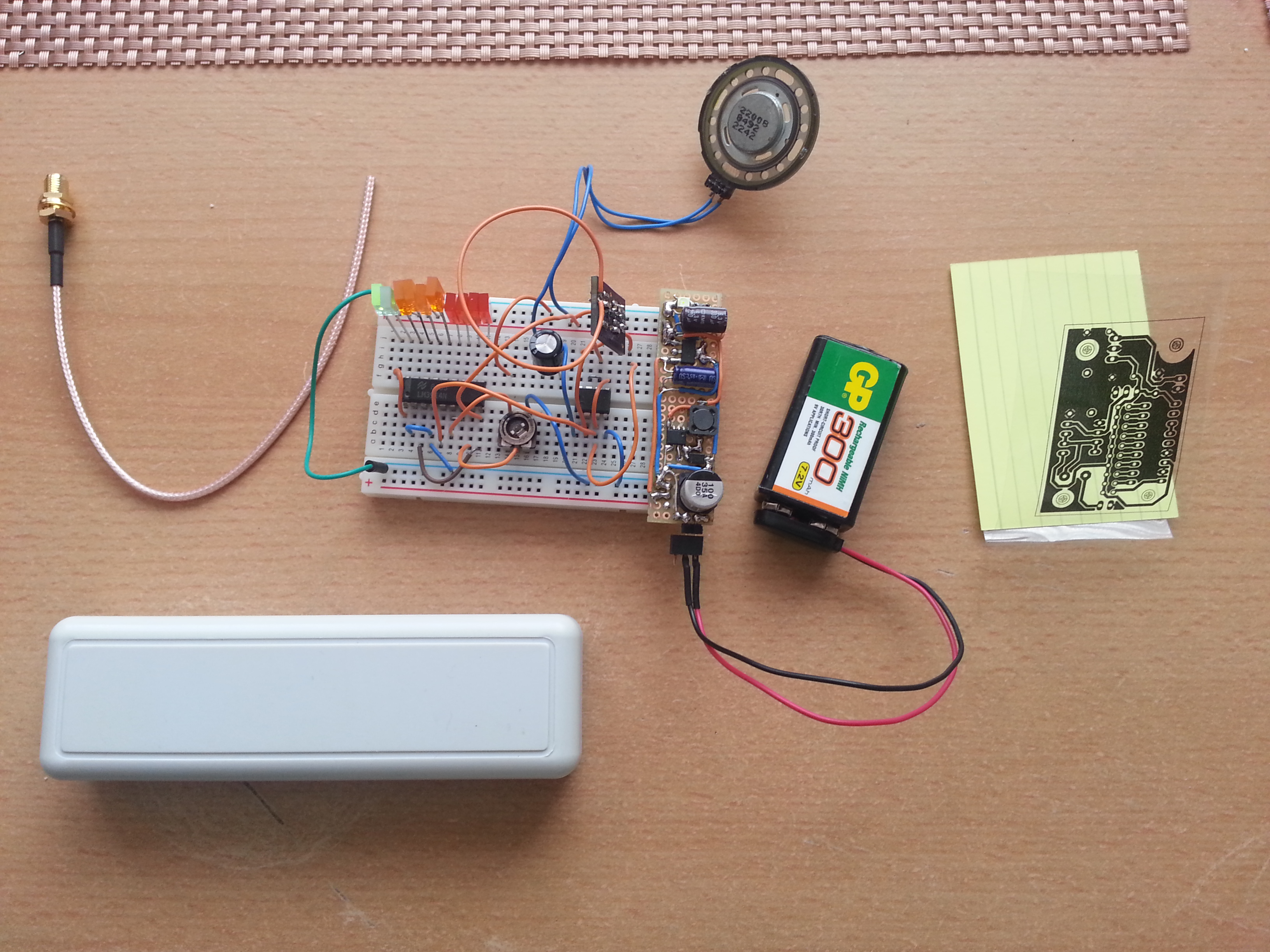
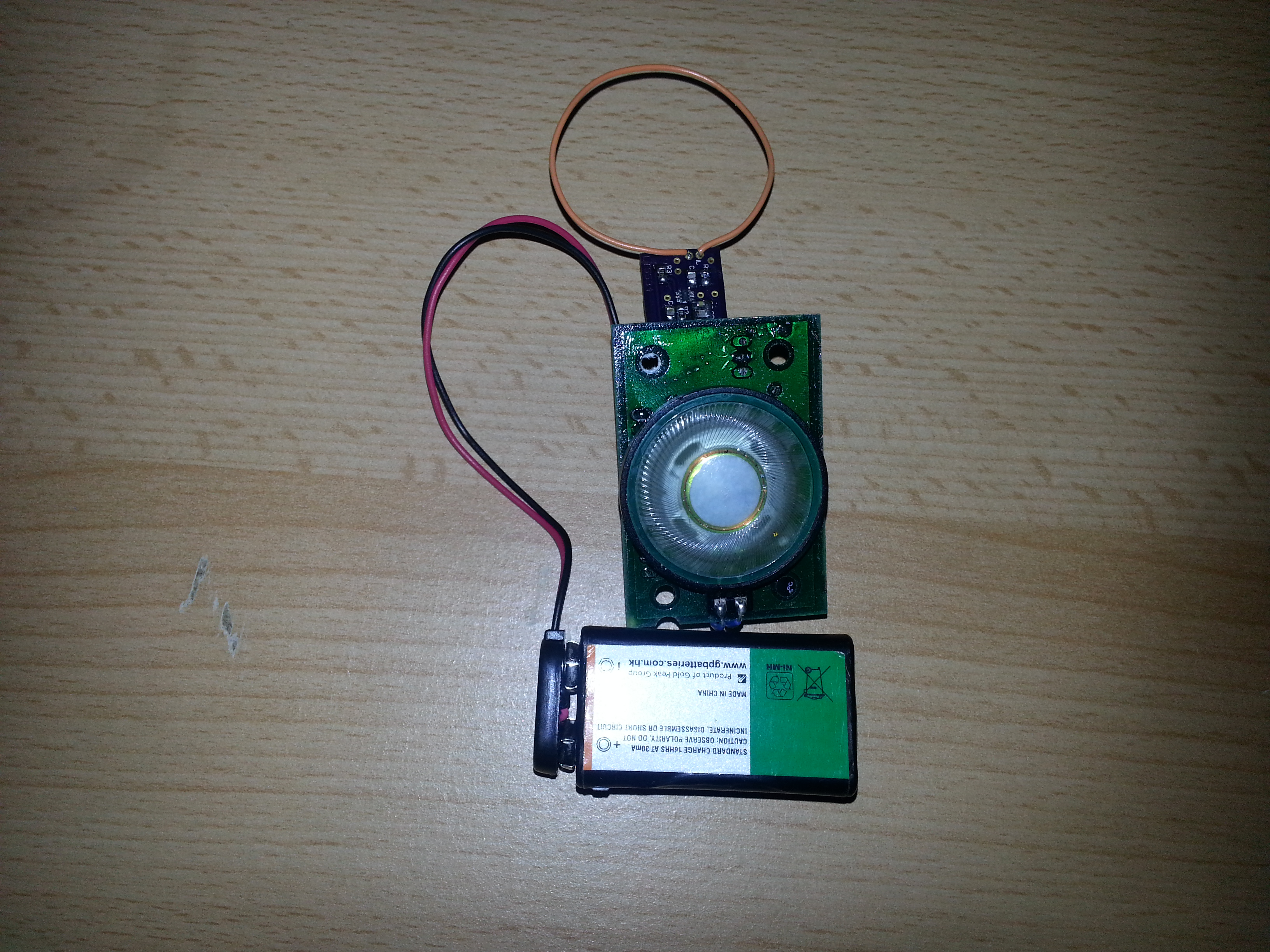
DIY PCB ready to be built into the project box:
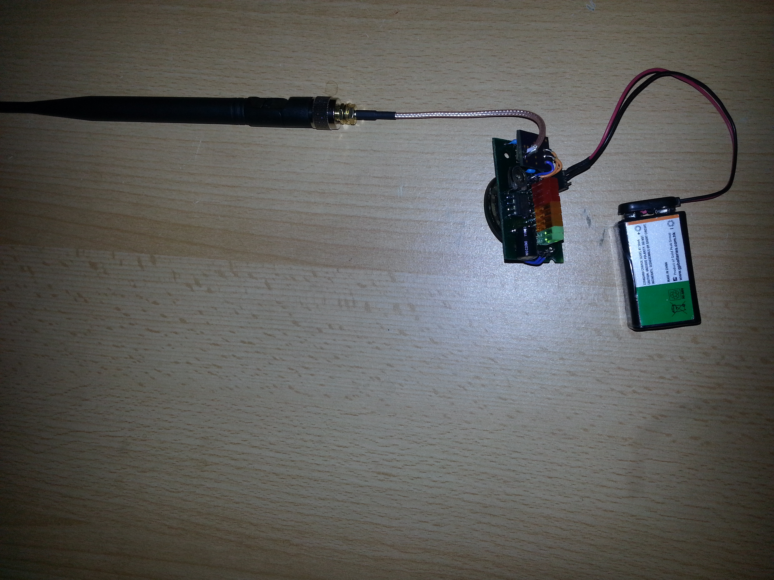
Now with loop antenna removed and SMA jack attached via coax pigtail.
Here are the modified schmatics and board files for the LT5534 carrier board:
LT5534 rf detector
Here is the board file and schematic for the bar graph and audio amplifier:
LM3914 rf signal strenth meter
Nicely done! Great project. I built a version myself with the LT5534. I would really like to get audible signals out as well, and an LED output would be awesome too. How did you use the op amp to get audio? I used an audio amp (TDA2822) but was only really hearing FM (or AM?) radio signals through the speaker. Not sure, but excess wires in/around the circuit (i.e. jumpers on a breadboard) could be problem..? I’m using a pretty short antenna wire. Not a lot of experience here, but I’m learning fast, and would appreciate any advice you have… or links to threads about this kind of thing.
Hey Mark,
I’m glad that you like the project! You can see in the schematic diagram how the opamp is connected to use it as an audio amplifier. It’s quite simple and requires only few additional parts. The configuration is called double buffer (2 amplifiers with a gain of 1 in parallel) which enables you to drive higher currents through the coil of the speaker. But using a TDA… chip is a good idea as well. You get even more output power.
What you heard was an AM radio station, since amplitude modulation doesn’t need any demodulation in this circuit in order to be heard correctly.
You can experiment with various antenna lengths for different frequency bands. Short antennas for high frequencies and longer ones for lower frequencies.
In RF circuits, especially like this one, almost everything can act like an additional antenna. Long ground wires and even your hand if it’s close to the antenna. If you want it to be more predictable, keep lead lengths short.
Greetings,
Arthur
I am interested in purchasing a functional unit with audio output.
What can I do to purchase one of your working prototypes?
Thanking you in advance.
Hello Arthur
I am looking to build the board of the LT5534. i have buy the chip and the PCBs from OSH Park but i have trouble choosing the other part like the 1nF capacitors 0805 as a example. i know the lt5534 work with the 5v of the arduino but when i want to buy the 1nF capacitors 0805 to i need to buy a 5v one or i can buy as example this one http://www.digikey.ca/product-detail/en/0805J1000102MXTE01/1608-1004-6-ND/5730421 that is 100 v. I am a bit confuse since I am not into electronic. I find in the LAB III tutorial i can not find all the information i need to know exactly the other part to buy.
1nF capacitors in 805 package
100nF capacitor in 805 package
10K ohm resistor in 805 package
47 ohm resistor in 805 package
Can you help! me thanks in advance for specification you can tell me.
Hi, in this case any ceramic capacitor in 0805 form factor will do since 5V is not a high voltage. The resistor is not critical either as long as it fits on the board
Hi can i build something like to pick signals from certian frequncies ie 500 to 505mhz only ? How do i do this thanks
Hello,
Great tutorial, having a little trouble getting my head around it, although I have ordered your boards via the shared projects on OSH park. How does the schematics change if I only want audio and no LED interface? Can I just exclude LM3914 or is this performing another function?
You should be able to exclude the LM3914