I’m using the Attiny85 quite a lot, especially since it’s programmable via the Arduino IDE. I like programming the AVR chips over an ISP programmer (USBtinyISP or USBASP). That way there’s no need for messing around with bootloaders.
After building a pogo pin adapter for the standard Atmel 6-pin ICSP header I needed a handy and tiny breakout board for some chips because I was tired of building the same circuit again and again and so this project was born. It contains all the essentials to be able to handle the Attiny85 in a SOIC-8 package conveniantly, such as reset pullup resistor, decoupling capacitors and an LED on PB0 (PWM pin). It’s tiny and can be left in small projects or used on a breadboard.


The eagle files can be found here:
Attiny85breakout
Category Archives: Arduino/Microcontrollers
builds and hacks including microcontrollers
MKL05Z32VFM4 Breakout Board
Having a reflow oven is a fantastic thing! Out of a sudden you can solder annoying IC packages with ease. I’ve been looking for a small and cheap ARM board with a 12bit ADC and low power options and came across the FRDM-KL05Z within the mbed envionment. This board only costs 11€ and besides the actual microcontroller (MKL05Z32VFM4) it has a MK20-based OpenSDA Interface which can do SWD and USB->UART on board which is a versatile tool for other microcontroller projects, in particular programming those cheap KL05Z chips. The mbed library has some example projects to demonstrate some things you can do with the chip, namely using different timers, the I2C accelerometer, PWM, interrupts and (very interesting) the built-in capacitive touch interface, which can also implement a slider. In conclusion, it’s a very interesting 32bit 48Mhz replacement for the Atmega328P which is used very often in small projects.
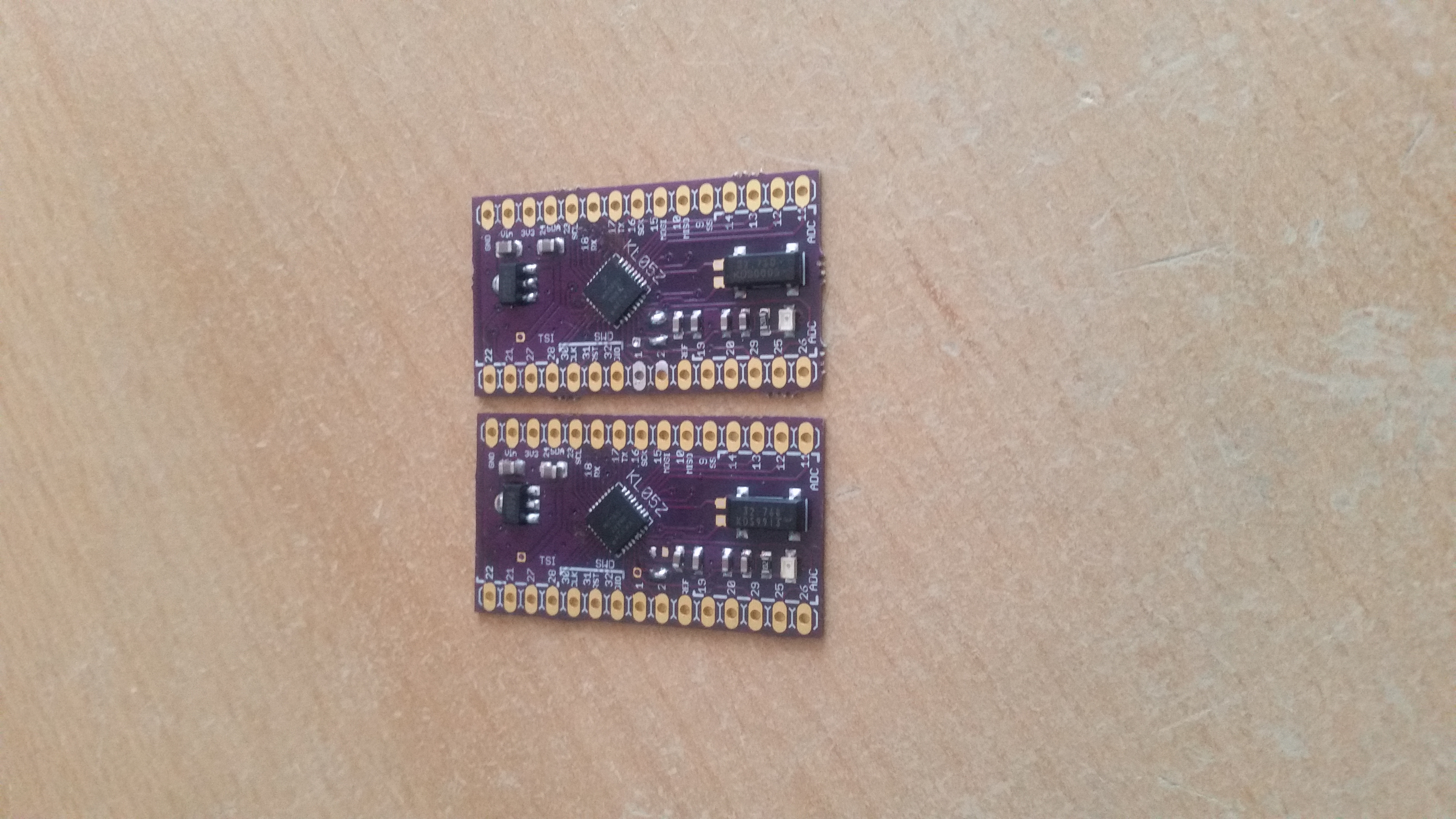
I’ve designed a board in eagle 7 (KL05Z design files) and ordered 3 samples from freescale. The board I had fabricated by OSH Park. The QFN32 (0.5mm pitch) reflowed really well with lead-free solder paste. Apply a thin string across each row of tiny pads, it doesn’t matter that the pads are “bridged”. The solder stop layer of the board and surface tension and flux of the paste resolve that for you. If you have bridges between the pads after reflowing, just apply a droplet of flux and touch them with the soldering iron tip. This corrects solder bridges easily without the use of solder wick! Yes, tiny pitch sizes have their advantages as well.
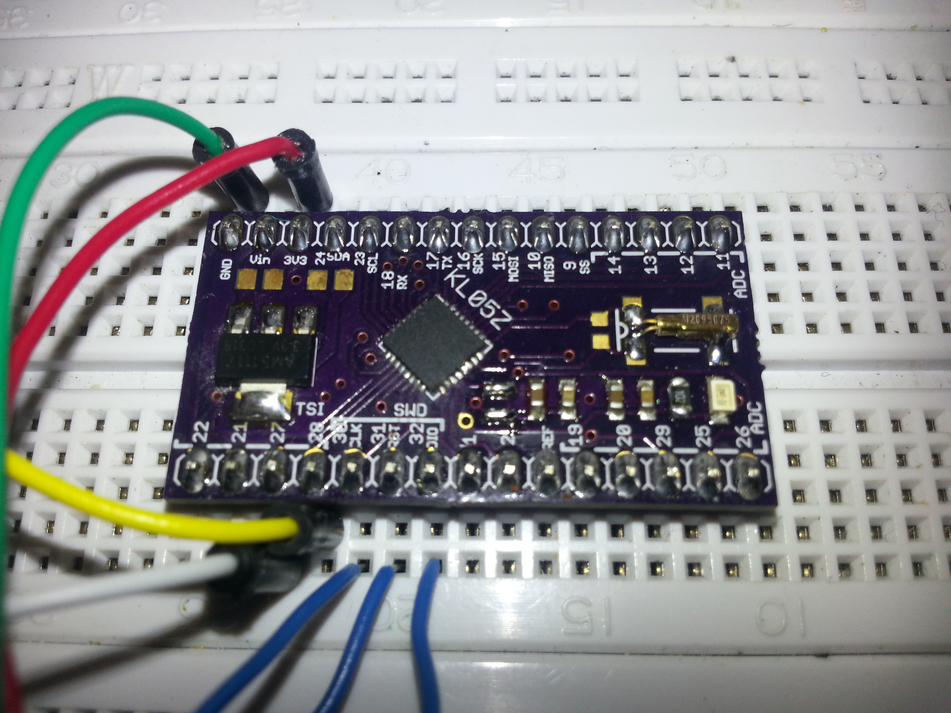
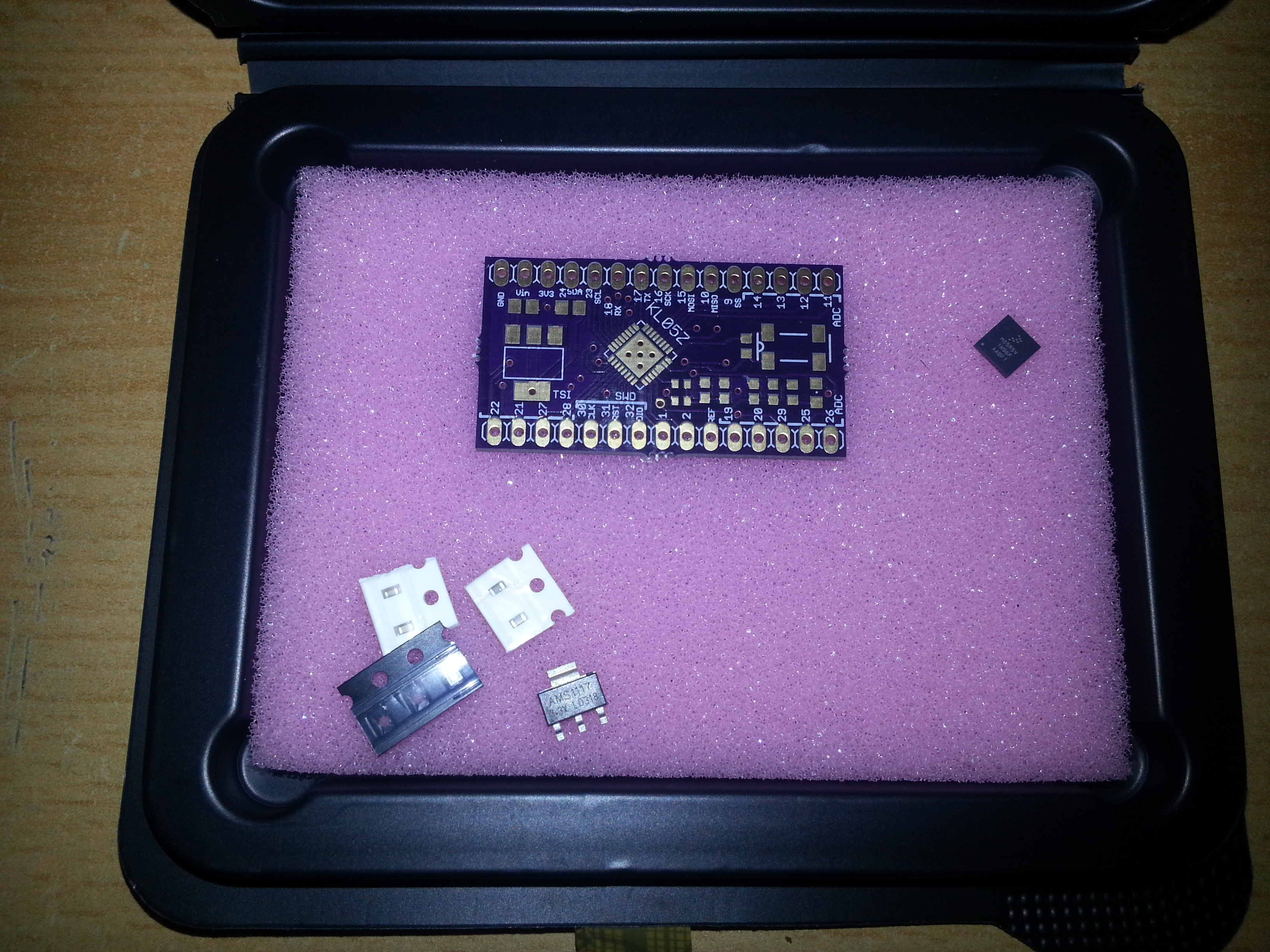
There are few other components on the board. 2 solder jumpers/0ohm resistors (the 0402 parts), 2x 1µF, 2x 100n (both 0603), 2x 10µF 0805, a 1k 0603 resistor, an 0603/0805 led at pin 11 (LED_RED in the mbed compiler), a voltage regulator and a watch crystal. Actually I didn’t quite feel the need of installing a reset button. You can hate me now for that………:-P But as there was plenty of room on the board, I built in a common AMS1117 3V3 regulator. Other voltages down to 1.8V can be dropped in as well. The footprint for the watch crystal allows a variety of different crystals to be intalled. No 22pf caps were installed in the FRDM board, so I left them out as well. The 10M resistor was included, but the circuit works fine without it. On the TOP side you have labels for pin numbers of the chips with their most common function within the mbed environment, while on the bottom side you find the port names of the pins. I haven’t included a 10-pin swd connector since the interface, besides power and ground, only consists of 3 pins (SWD_CLK, SWD_DIO and RST_TGTMCU) which you can connect with jumper wire just as easily. The wires for the three signals were soldered to J1 directly.

Programming can be done with a hacked FRDM board via mbed compiler. I’m saying hacked because there is a bug on the board that has to be fixed by cutting a trace in order to be able to program an off-board chip. By cutting a trace I don’t mean cutting the trace below the J6 jumper as the manual states. This jumper is completely useless! It’s supposed to disconnent the onboard target KL05Z from the SWD_CLK but it does not!! Just leave it in place and cut the trace right next to the MCU, running from pin 30 of the KL05Z to the next via (see the orange circle in the pic below):
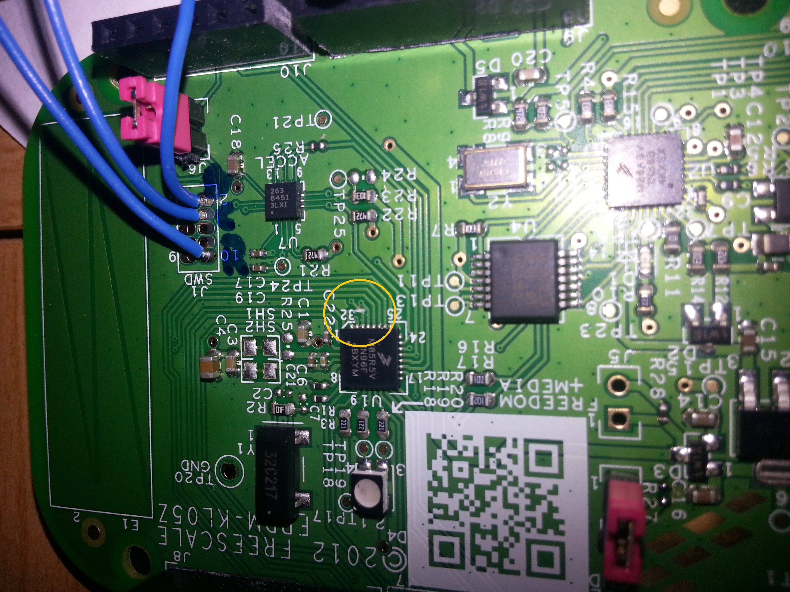
Be very careful not to cut other traces. In case you’ll want to use the on board chip again, the solder mask on the trace will have to be exposed carefully an a tiny jumper will have to be inserted in some way. However at the moment I’m fine with my breakout boards.
Finally, a link to all relevant ducuments for the FRDM-KL05Z: FRDM-KL05Z freescale documentation page with schematics etc.
Update: improved and debugged version with a better voltage regulator:
KL05Z1.1
DIY Reflow Oven
Nowadays anyone can order cheap professionally manufactured PCBs from one’s own designs, as well as Kapton stencils from OSH Park (https://www.oshstencils.com/). This inspired me to take my electronics skills to the next level by building a temperature-controlled reflow oven out of a small toaster oven after I’ve been into 3D printing for quite a while. I’ve been gathering parts slowly for some time and one day a 40A solid state relay (which is overkill for this particular project), a K type thermocouple with MAX6675 amplifier (which has been discontinued to be replaced with the MAX31855) and some standard components have united to form this lovely tool.
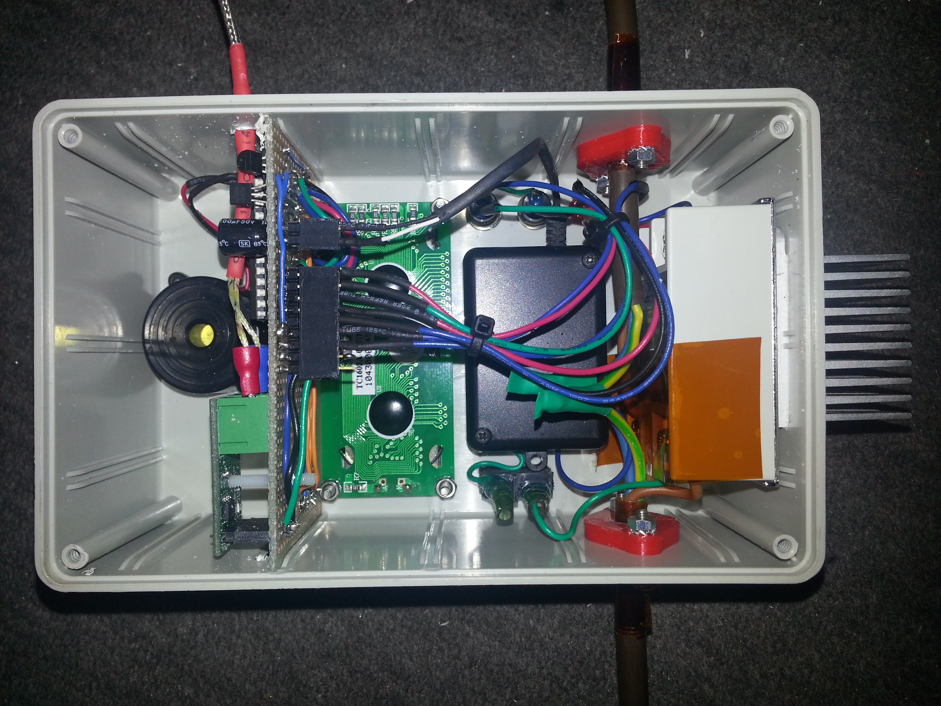
I’ve constructed my oven controller to be compatible with the Reflow Oven Controller Shield project by Rocketscream, since the algorithm is well-tested and versatile. A minimal Arduino configuration on a perfboard was built to fit into the PCB slots of a strapubox enclosure. A standard 16×2 LCD and a button form the user interface. The SSR has got a heatsink but doesn’t even get warm with the small oven which draws <2 Amps. The electronics is powered by a samsung phone charger which has been fitted into the small black enclosure for perfect insulation. It's a small switching power supply capable of delivering 5V @ 750mA. The red parts on the input/output power cable are self-designed and 3D printed strain reliefs for the thick cable
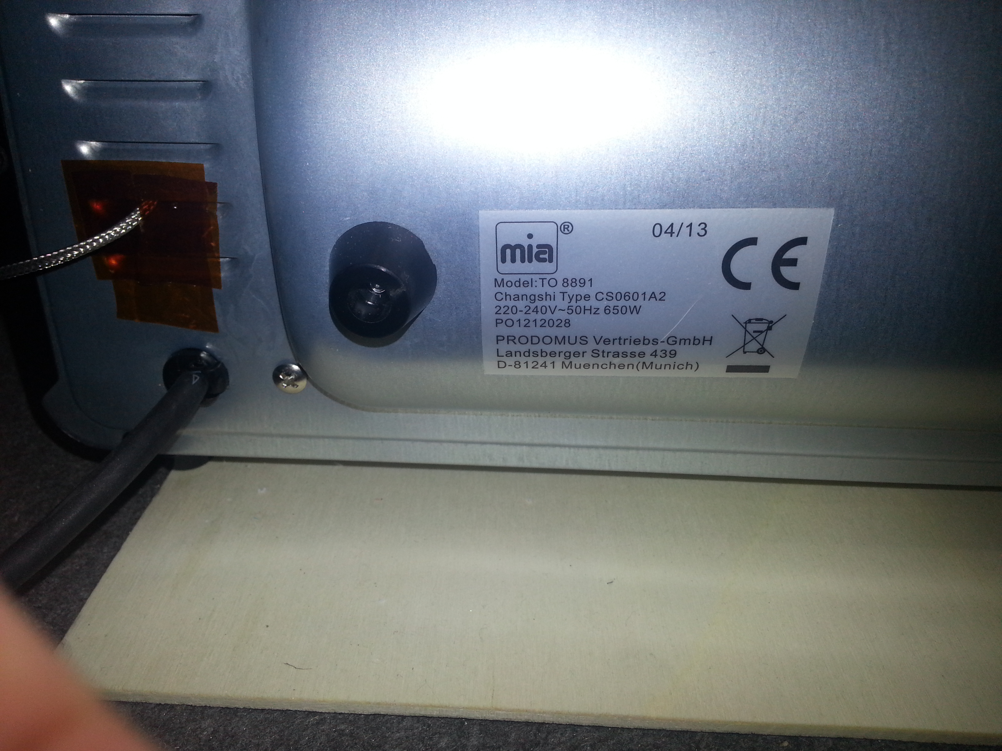
The oven is the smallest and cheapest toaster oven I could find. It has got a top and a bottom 350W heating element (the ceramic white ones that are supposed to be better for reflow purposes) and cost about 19€ in Berlet.
The heating elements are covered with slotted sheet metal, which should avoid direct exposure of the foods/PCBs to the infrared/heat radiation I suppose. I’ve removed all the “guts” from the original oven and wired the two elements in parallel. The mains cable has been left in place. A hole for the thermocouple has been drilled on the side of the inside wall.
First dry-run tests with the included baking tray resulted in the following temperature profile:
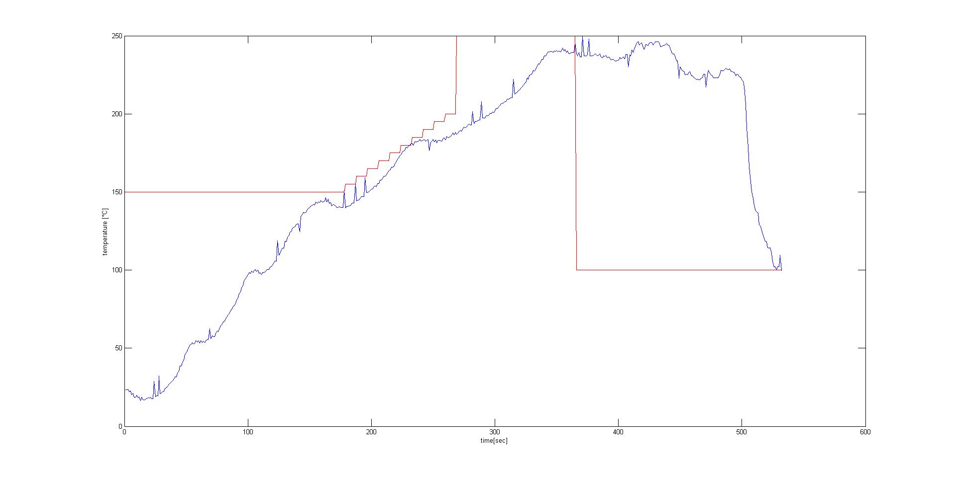
The software transmits the temperature value measured by the thermocouple via serial, which it does every second. I simply inserted a bluetooth module into the FTDI header, saved the values in a terminal program on a paired PC and plotted them with MATLAB. Attempts without baking tray resulted in quicker responses in measured temperature due to the lower thermal mass.
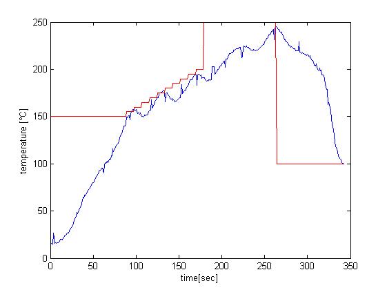
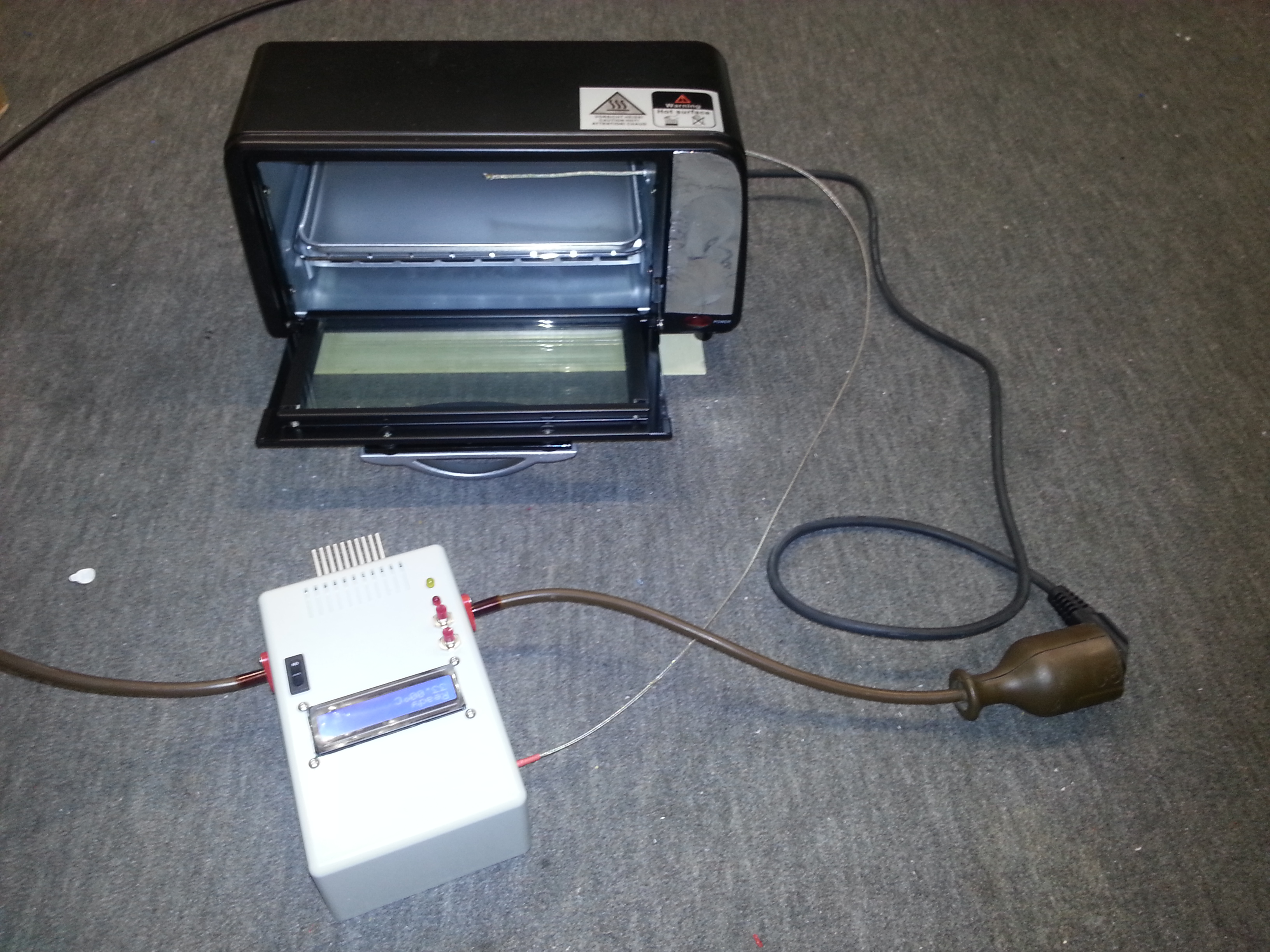
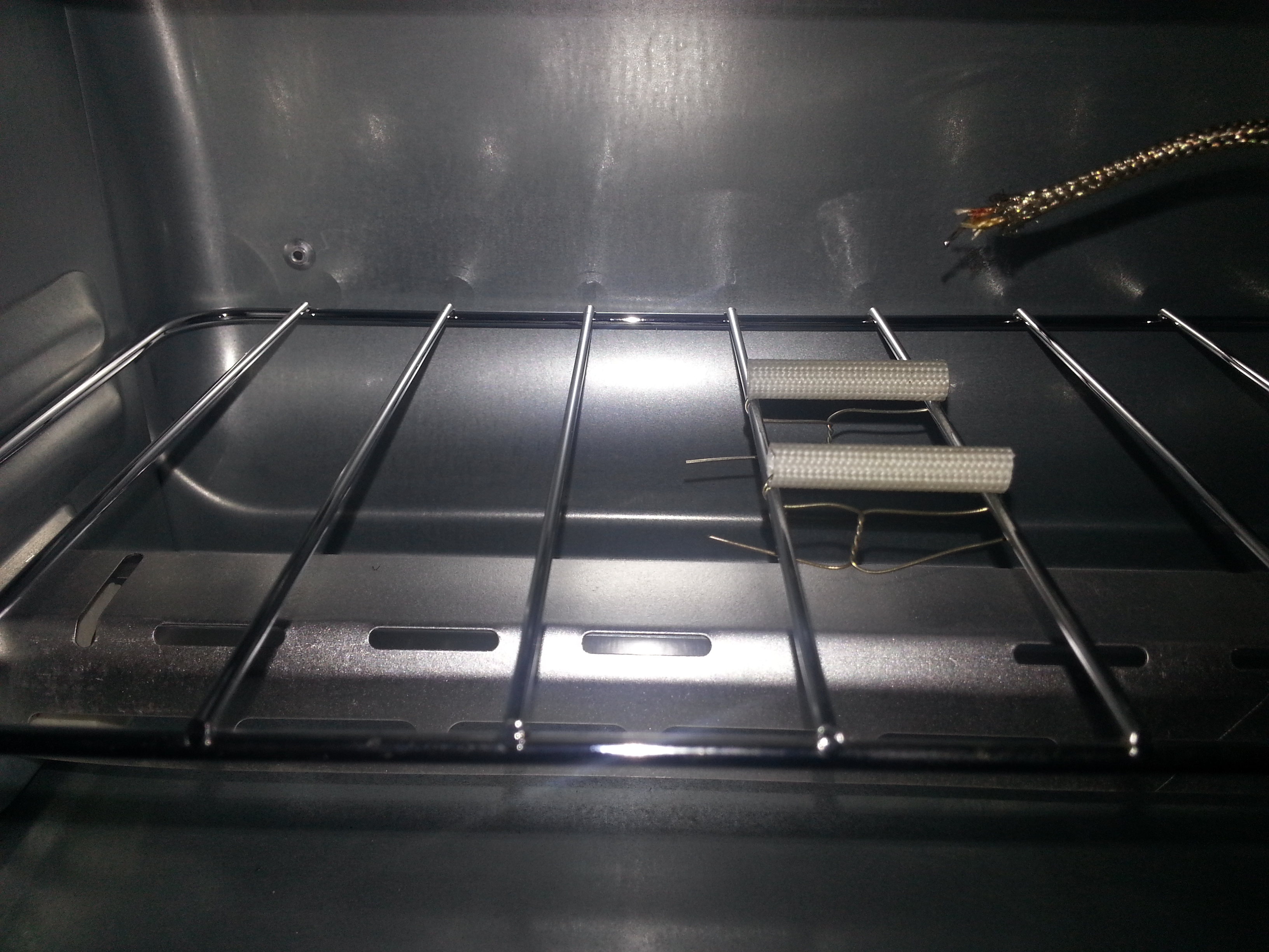
I decided to solder my boards without tray to have more control over the temperature on the board, since the oven doesn’t have a convection fan. To have as little thermal mass under the board as possible I installed two heat-resistant insulation sleeves. The end of the thermocouple can be lowered to touch the PCB directly by moving its wire outsie of the oven. This gives you better measurements of the temperature that the parts and the board surface are exposed to. I removed the metal shell on the end of the thermocouple to further reduce its thermal mass.
This is the setup that works best so far. The project is a full success. I’m very pleased with the rocketscream algorithm, my controller and the tiny oven. First results with lead-free solderpaste were close to perfect.
Plot Clock w/ DS1307 RTC

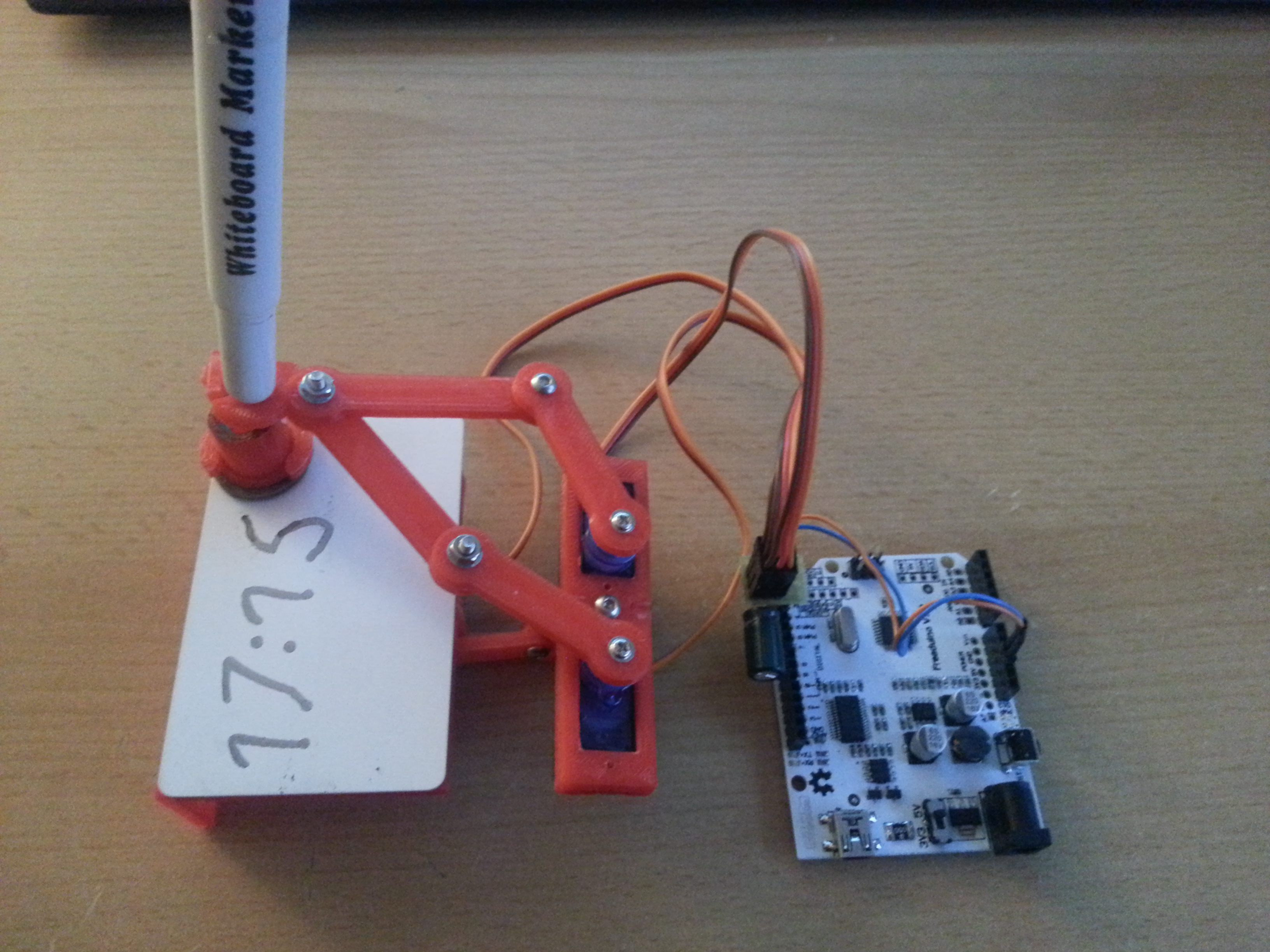
I’ve printed the parts for a Plot Clock in PLA and assembled it in a pretty much standard configuration, which worked great. Quite a bit of filing and sanding was necessary, but it was worth it, the final device was quite easy to calibrate. The only thing I found was missing is time keeping capability, so I added a DS1307 I2C real time clock module, which is a straightforward procedure. Learn how to set up the RTC HERE.
Before you run the sketch that sets the time on the RTC, make sure to remove the battery once to reset the DS1307. Put the battery back in and run the sketch. My modification on the Plot Clock code simply fetches the time once every time you power the arduino up. Further timekeeping is done by the ATmega.
// Plotclock
// cc - by Johannes Heberlein 2014
// v 1.01
// thingiverse.com/joo   wiki.fablab-nuernberg.de

// units: mm; microseconds; radians
// origin: bottom left of drawing surface

// time library see http://playground.arduino.cc/Code/time

// Date and time functions using a DS1307 RTC connected via I2C and Wire lib

    #include <Wire.h>
    #include "RTClib.h"

    RTC_DS1307 RTC;

// delete or mark the next line as comment when done with calibration
//#define CALIBRATION

// When in calibration mode, adjust the following factor until the servos move exactly 90 degrees
#define SERVOFAKTOR 555

// Zero-position of left and right servo
// When in calibration mode, adjust the NULL-values so that the servo arms are at all times parallel
// either to the X or Y axis
#define SERVOLEFTNULL 2075
#define SERVORIGHTNULL 1065

#define SERVOPINLIFT  2
#define SERVOPINLEFT  3
#define SERVOPINRIGHT 4

// lift positions of lifting servo
#define LIFT0 1350 // on drawing surface
#define LIFT1 1180// between numbers
#define LIFT2 850  // going towards sweeper

// speed of liftimg arm, higher is slower
#define LIFTSPEED 1500

// length of arms
#define L1 35
#define L2 55.1
#define L3 13.2


// origin points of left and right servo
#define O1X 22
#define O1Y -25
#define O2X 47
#define O2Y -25


#include <Time.h> // see http://playground.arduino.cc/Code/time
#include <Servo.h>

int servoLift = 1500;

Servo servo1;  //
Servo servo2;  //
Servo servo3;  //

volatile double lastX = 75;
volatile double lastY = 47.5;

int last_min = 0;

void setup()
{

  Wire.begin();
  RTC.begin();
  DateTime now = RTC.now();
  // Set current time only the first to values, hh,mm are needed
  int rhour = now.hour();
  int rminute = now.minute();
  setTime(rhour,rminute,0,0,0,0);

  drawTo(75.2, 47);
  lift(0);
  servo1.attach(SERVOPINLIFT);  //  lifting servo
  servo2.attach(SERVOPINLEFT);  //  left servo
  servo3.attach(SERVOPINRIGHT);  //  right servo

  delay(1000);


}

void loop()
{

#ifdef CALIBRATION

  // Servohorns will have 90° between movements, parallel to x and y axis
  drawTo(-3, 29.2);
  delay(500);
  drawTo(74.1, 28);
  delay(500);

#else
  //DateTime now = RTC.now();

  int i = 0;
  if (last_min != minute()) {

    if (!servo1.attached()) servo1.attach(SERVOPINLIFT);
    if (!servo2.attached()) servo2.attach(SERVOPINLEFT);
    if (!servo3.attached()) servo3.attach(SERVOPINRIGHT);

    lift(0);

    hour();


    while ((i+1)*10 <= hour())
    {
      i++;
    }

    number(3, 3, 111, 1);
    number(5, 25, i, 0.9);
    number(19, 25, (hour()-i*10), 0.9);
    number(28, 25, 11, 0.9);

    i=0;
    while ((i+1)*10 <= minute())
    {
      i++;
    }
    number(34, 25, i, 0.9);
    number(48, 25, (minute()-i*10), 0.9);
    lift(2);
    drawTo(74.2, 47.5);
    lift(1);
    last_min = minute();

    servo1.detach();
    servo2.detach();
    servo3.detach();
  }

#endif

}

// Writing numeral with bx by being the bottom left originpoint. Scale 1 equals a 20 mm high font.
// The structure follows this principle: move to first startpoint of the numeral, lift down, draw numeral, lift up
void number(float bx, float by, int num, float scale) {

  switch (num) {

  case 0:
    drawTo(bx + 12 * scale, by + 6 * scale);
    lift(0);
    bogenGZS(bx + 7 * scale, by + 10 * scale, 10 * scale, -0.8, 6.7, 0.5);
    lift(1);
    break;
  case 1:

    drawTo(bx + 3 * scale, by + 15 * scale);
    lift(0);
    drawTo(bx + 10 * scale, by + 20 * scale);
    drawTo(bx + 10 * scale, by + 0 * scale);
    lift(1);
    break;
  case 2:
    drawTo(bx + 2 * scale, by + 12 * scale);
    lift(0);
    bogenUZS(bx + 8 * scale, by + 14 * scale, 6 * scale, 3, -0.8, 1);
    drawTo(bx + 1 * scale, by + 0 * scale);
    drawTo(bx + 12 * scale, by + 0 * scale);
    lift(1);
    break;
  case 3:
    drawTo(bx + 2 * scale, by + 17 * scale);
    lift(0);
    bogenUZS(bx + 5 * scale, by + 15 * scale, 5 * scale, 3, -2, 1);
    bogenUZS(bx + 5 * scale, by + 5 * scale, 5 * scale, 1.57, -3, 1);
    lift(1);
    break;
  case 4:
    drawTo(bx + 10 * scale, by + 0 * scale);
    lift(0);
    drawTo(bx + 10 * scale, by + 20 * scale);
    drawTo(bx + 2 * scale, by + 6 * scale);
    drawTo(bx + 12 * scale, by + 6 * scale);
    lift(1);
    break;
  case 5:
    drawTo(bx + 2 * scale, by + 5 * scale);
    lift(0);
    bogenGZS(bx + 5 * scale, by + 6 * scale, 6 * scale, -2.5, 2, 1);
    drawTo(bx + 5 * scale, by + 20 * scale);
    drawTo(bx + 12 * scale, by + 20 * scale);
    lift(1);
    break;
  case 6:
    drawTo(bx + 2 * scale, by + 10 * scale);
    lift(0);
    bogenUZS(bx + 7 * scale, by + 6 * scale, 6 * scale, 2, -4.4, 1);
    drawTo(bx + 11 * scale, by + 20 * scale);
    lift(1);
    break;
  case 7:
    drawTo(bx + 2 * scale, by + 20 * scale);
    lift(0);
    drawTo(bx + 12 * scale, by + 20 * scale);
    drawTo(bx + 2 * scale, by + 0);
    lift(1);
    break;
  case 8:
    drawTo(bx + 5 * scale, by + 10 * scale);
    lift(0);
    bogenUZS(bx + 5 * scale, by + 15 * scale, 5 * scale, 4.7, -1.6, 1);
    bogenGZS(bx + 5 * scale, by + 5 * scale, 5 * scale, -4.7, 2, 1);
    lift(1);
    break;

  case 9:
    drawTo(bx + 9 * scale, by + 11 * scale);
    lift(0);
    bogenUZS(bx + 7 * scale, by + 15 * scale, 5 * scale, 4, -0.5, 1);
    drawTo(bx + 5 * scale, by + 0);
    lift(1);
    break;

  case 111:

    lift(0);
    drawTo(70, 46);
    drawTo(65, 43);

    drawTo(65, 49);
    drawTo(5, 49);
    drawTo(5, 45);
    drawTo(65, 45);
    drawTo(65, 40);

    drawTo(5, 40);
    drawTo(5, 35);
    drawTo(65, 35);
    drawTo(65, 30);

    drawTo(5, 30);
    drawTo(5, 25);
    drawTo(65, 25);
    drawTo(65, 20);

    drawTo(5, 20);
    drawTo(60, 44);

    drawTo(75.2, 47);
    lift(2);

    break;

  case 11:
    drawTo(bx + 5 * scale, by + 15 * scale);
    lift(0);
    bogenGZS(bx + 5 * scale, by + 15 * scale, 0.1 * scale, 1, -1, 1);
    lift(1);
    drawTo(bx + 5 * scale, by + 5 * scale);
    lift(0);
    bogenGZS(bx + 5 * scale, by + 5 * scale, 0.1 * scale, 1, -1, 1);
    lift(1);
    break;

  }
}


void lift(char lift) {
  switch (lift) {
    // room to optimize  !

  case 0: //850

      if (servoLift >= LIFT0) {
      while (servoLift >= LIFT0)
      {
        servoLift--;
        servo1.writeMicroseconds(servoLift);
        delayMicroseconds(LIFTSPEED);
      }
    }
    else {
      while (servoLift <= LIFT0) {
        servoLift++;
        servo1.writeMicroseconds(servoLift);
        delayMicroseconds(LIFTSPEED);

      }

    }

    break;

  case 1: //150

    if (servoLift >= LIFT1) {
      while (servoLift >= LIFT1) {
        servoLift--;
        servo1.writeMicroseconds(servoLift);
        delayMicroseconds(LIFTSPEED);

      }
    }
    else {
      while (servoLift <= LIFT1) {
        servoLift++;
        servo1.writeMicroseconds(servoLift);
        delayMicroseconds(LIFTSPEED);
      }

    }

    break;

  case 2:

    if (servoLift >= LIFT2) {
      while (servoLift >= LIFT2) {
        servoLift--;
        servo1.writeMicroseconds(servoLift);
        delayMicroseconds(LIFTSPEED);
      }
    }
    else {
      while (servoLift <= LIFT2) {
        servoLift++;
        servo1.writeMicroseconds(servoLift);
        delayMicroseconds(LIFTSPEED);
      }
    }
    break;
  }
}


void bogenUZS(float bx, float by, float radius, int start, int ende, float sqee) {
  float inkr = -0.05;
  float count = 0;

  do {
    drawTo(sqee * radius * cos(start + count) + bx,
    radius * sin(start + count) + by);
    count += inkr;
  }
  while ((start + count) > ende);

}

void bogenGZS(float bx, float by, float radius, int start, int ende, float sqee) {
  float inkr = 0.05;
  float count = 0;

  do {
    drawTo(sqee * radius * cos(start + count) + bx,
    radius * sin(start + count) + by);
    count += inkr;
  }
  while ((start + count) <= ende);
}


void drawTo(double pX, double pY) {
  double dx, dy, c;
  int i;

  // dx dy of new point
  dx = pX - lastX;
  dy = pY - lastY;
  //path lenght in mm, times 4 equals 4 steps per mm
  c = floor(4 * sqrt(dx * dx + dy * dy));

  if (c < 1) c = 1;

  for (i = 0; i <= c; i++) {
    // draw line point by point
    set_XY(lastX + (i * dx / c), lastY + (i * dy / c));

  }

  lastX = pX;
  lastY = pY;
}

double return_angle(double a, double b, double c) {
  // cosine rule for angle between c and a
  return acos((a * a + c * c - b * b) / (2 * a * c));
}

void set_XY(double Tx, double Ty)
{
  delay(1);
  double dx, dy, c, a1, a2, Hx, Hy;

  // calculate triangle between pen, servoLeft and arm joint
  // cartesian dx/dy
  dx = Tx - O1X;
  dy = Ty - O1Y;

  // polar lemgth (c) and angle (a1)
  c = sqrt(dx * dx + dy * dy); //
  a1 = atan2(dy, dx); //
  a2 = return_angle(L1, L2, c);

  servo2.writeMicroseconds(floor(((a2 + a1 - M_PI) * SERVOFAKTOR) + SERVOLEFTNULL));

  // calculate joinr arm point for triangle of the right servo arm
  a2 = return_angle(L2, L1, c);
  Hx = Tx + L3 * cos((a1 - a2 + 0.621) + M_PI); //36,5°
  Hy = Ty + L3 * sin((a1 - a2 + 0.621) + M_PI);

  // calculate triangle between pen joint, servoRight and arm joint
  dx = Hx - O2X;
  dy = Hy - O2Y;

  c = sqrt(dx * dx + dy * dy);
  a1 = atan2(dy, dx);
  a2 = return_angle(L1, (L2 - L3), c);

  servo3.writeMicroseconds(floor(((a1 - a2) * SERVOFAKTOR) + SERVORIGHTNULL));

}
RAMPS 1.4 on the Velleman K8200
After sending my original Velleman K8200 control board to circuit board heaven where it probably met up with the other A4988 chips I’ve burned in the past, I finally received a RAMPS 1.4 shield, a set of new stepper drivers (which already carried small heatsinks), the RepRapDiscount Full Graphic Smart Controller and an Arduino Mega.
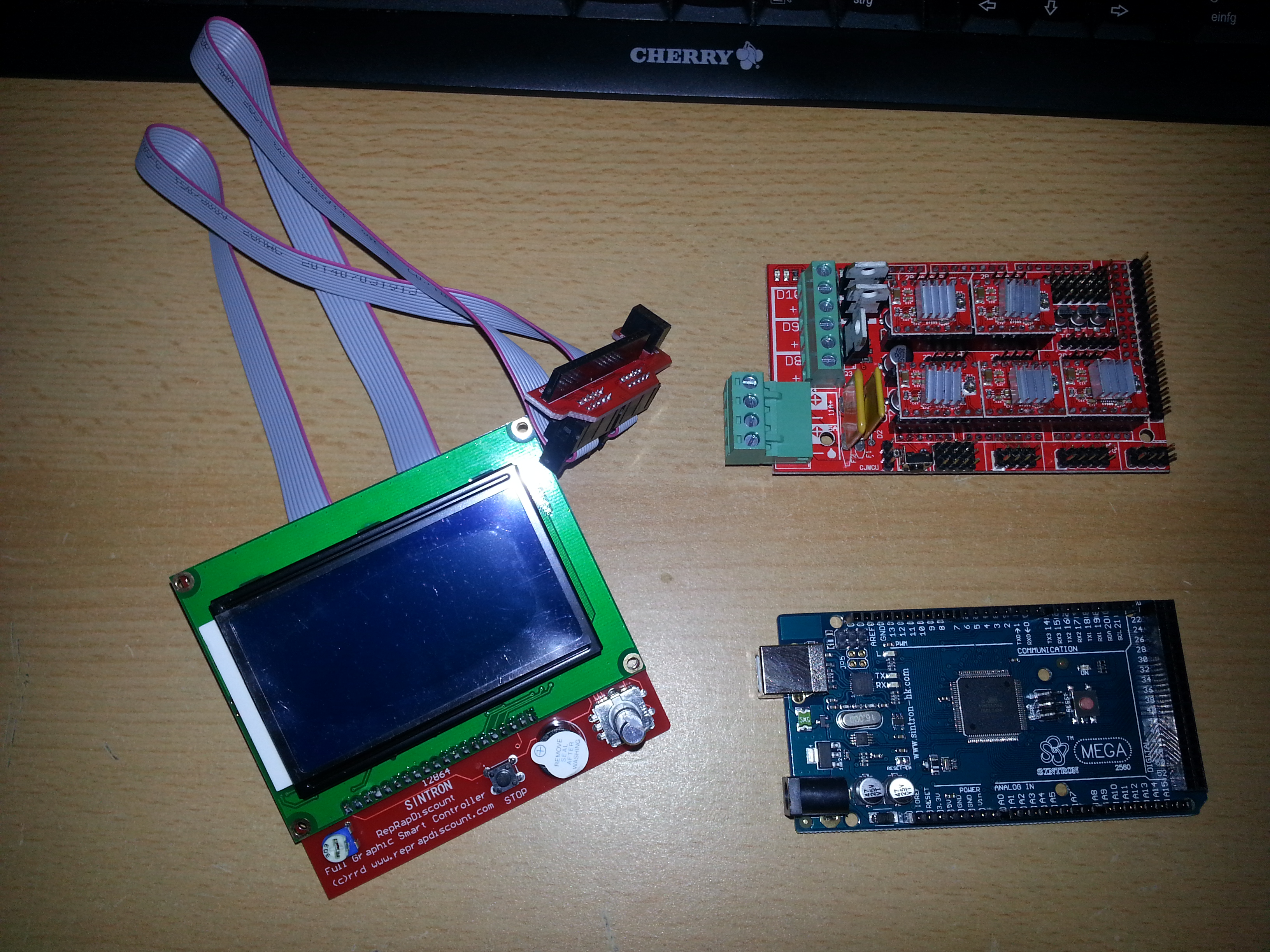
The boards I got were manufactured, sold and labeled by a company called Sintron and are very high quality boards I have to say. Now the journey of resuscitating my 3D printer could finally continue.
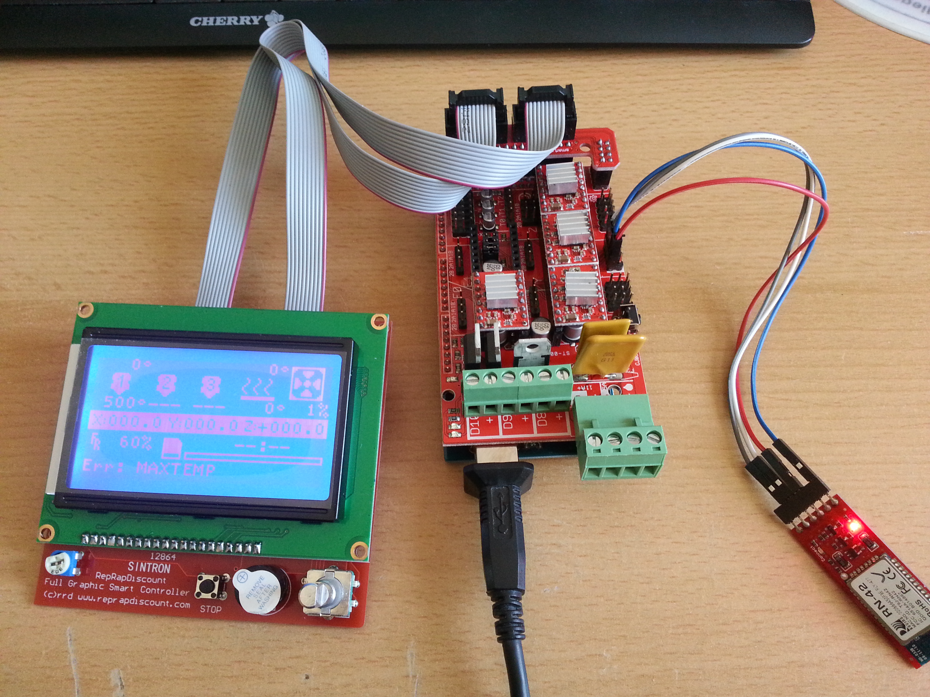
Fist of all some adapter cables have to be made. The RAMPS 1.4 shield has got terminal blocks for the heatbed, extruder and fan. You have to select in firmware, which configuration you want to have for your shield. One pair of blocks is fused with a 11 Ampère fuse and is meant to power the heatbed, the other two can be configured. Use large wires and 4 2.54mm header pins, 2 for + and 2 for minus because the currents are pretty high here. One bridge cable is needed between the 5A and the 11A positive terminal if you want to use the Velleman power supply. Adapter cables are also needed for the endstop switches. I simply used male-female extension jumper wires and attached them so that they pull to GND when pressed. The Velleman female connectors for the stepper motors and thermistors that were there already fit on the RAMPS 1.4 directly and do not reqire adapter cables. After flashing a raw standard vesion of Marlin it turned out that the stepper motors for X, Z and the extruder were reversed. Out of liziness I swapped the red and green wire on the connectors for those and didn’t have to change anything in Marlin. The crimped connectors can be pulled out of the plastic enclosure by pressing down the tiny hook on them with a small nail. There is a nice connection diagram on the RAMPS 1.4 page.
You can remove the driver for the second extruder if you’re not using it and keep it as a replacement part.
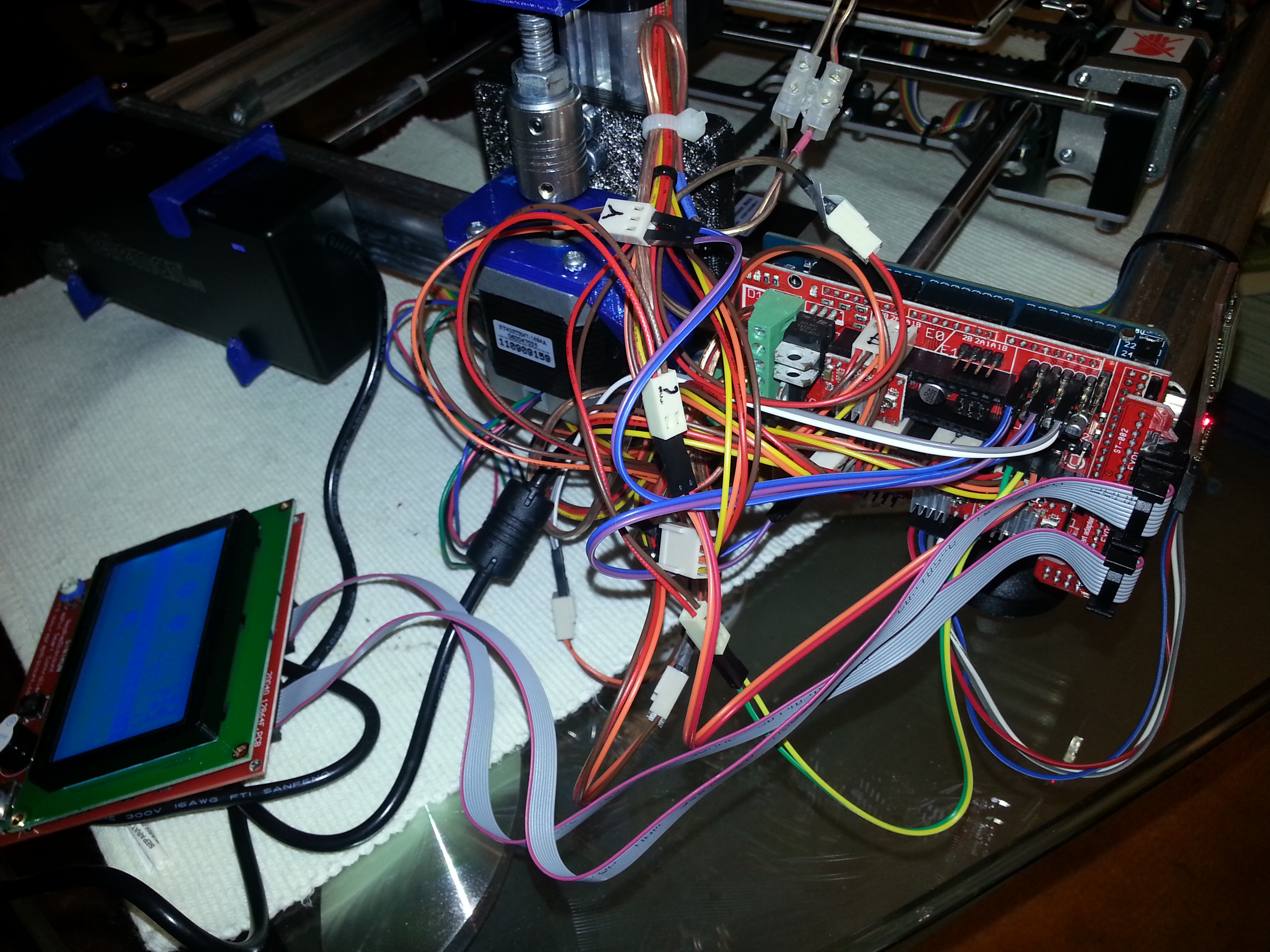
Next, the stepper motor current has to be set. The drivers I got didn’t seem to have the exposed via to measure motor voltage and so I did it the good ol’way: by listening and turning the pot. The louder the hissing of the motor, the higher the current. What’s interesting is that sometimes you seem to receive radio stations on the stepper motor driver 😀 Presumably it’s AM radio. Fascinating! What I’ve also done is removed the small heat sinks from the X,Y,Z and E drivers and covering the entire PCB of the motor drivers with a strip of Kapton tape and cut out the outline of the A4988 chip with a sharpie knife. Then I reattached the heat sinks. I noticed that that they tend to sink down when you mount the board horizontally upright. That’s why the’re called heat sinks.. Haha. The Kapton just prevents the header pins of the drivers from being shorted out by the heat sink at some point, since the printer vibrates during operation.
I’ve attached a small heatsink to the bottom of the Arduino Mega board right beneath the linear regulator, since it has to drop 15V down to 5V and therefore produces an immense amount of heat. With the heatsink it seems to be fine so far.
Pretty much everything else has to be adjusted in the Configuation.h file in Marlin. Here is my Configuration.h file. The main changes I have made are:
1. selecting the proper board with the extruder-fan-heatbed configuration
2. inverting the endstops
3. selecting the RepRapDiscount Full Graphic Smart Controller
4. enabling SD card support
5. changing the baud rate to 115200 in order to connect a bluetooth module
6. setting the right steps per mm for all axes
7. lowering accelerations. That’s right. I wanted to try accelerations of 500mm/s^2 and observe their impact on print quality, since the K8200/3DRAG is built in X-Y-Table configuration and the motors (especially X) have to accelerate a larger mass than in other printers. Also, I will try printing with lower speeds in the future.
8. Is this it?
EDIT: download my complete Marlin version here: Marlin_K8200_GLCDmod
Of course you need to download and install the u8glib Arduino Library prior to uploading. I used version 1.5.
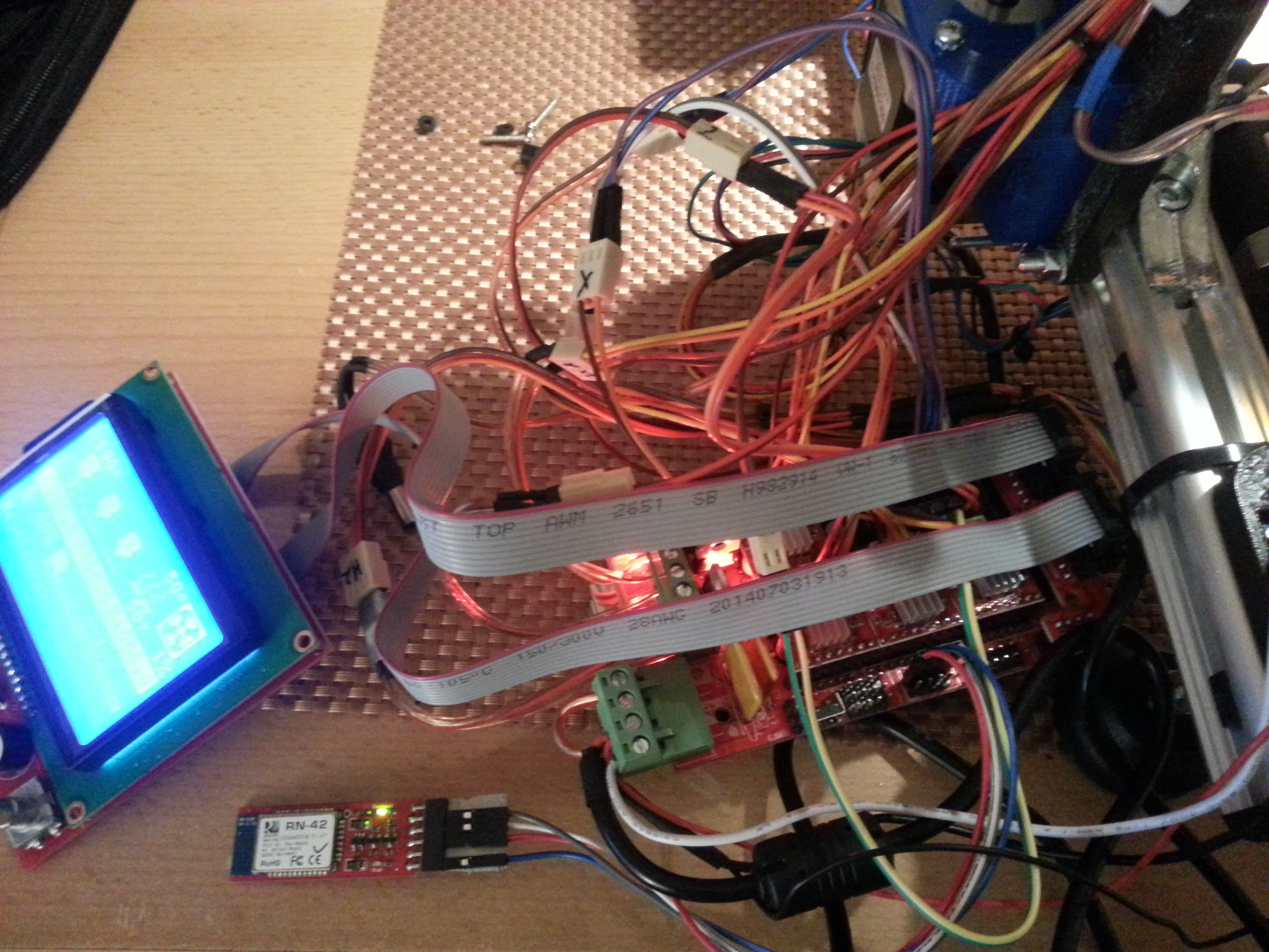
All in all I’m very pleased with the RAMPS 1.4 upgrade. The controller offers you the the possibility to adjust print speed on the fly (among many other settings) and print from the SD card without any problems. The system is almost plug and play and can be further extended. For example a wireless option can be added. I’ve attached a Bluetooth Mate Silver right now, which has level shifters on the TR and RX lines and is therefore 5v-compatible. You can print from RepetierHost directly over the air or control the printer over an Android device both without any problems. There’s an app around already and I’m thinking about writing my own…Also I’m considering testing Xbee for a longer range.
RFM23BP Breakout Board
Breakout boards for the HopeRF RFM23BP 433MHz modules with SMA connectors. Fabricated by the famous Magic Purple PCB Factory 😉
These modules come in different operating frequencies and are supposed to transmit with up to 1W. They communicate via SPI and need up to 600mA (max. output power). The power can be set in software. I made them for long range telemetry purposes, but will not operate them at full power, since a license is needed for output powers above 10mW, even in the free ISM (Industrial, Scientific and Medical) band.
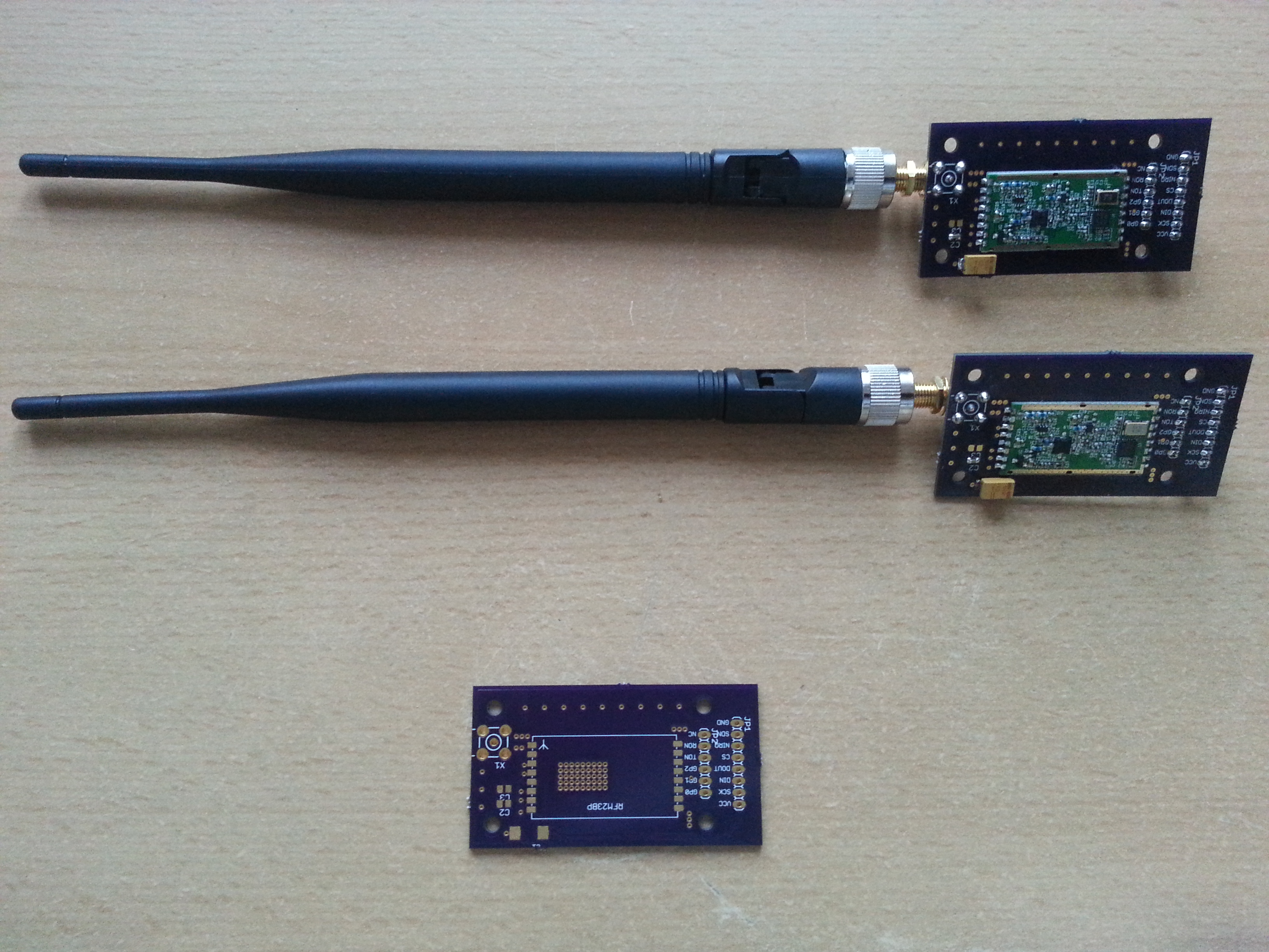
The modules have a blank ground plane without solder mask on the bottom side. A special soldering technique was used here: I tinned this blank area and filled all those vias on the breakout board with solder. Then I applied flux to both the module and the board and finally soldered them together by holding the sandwich against my cooking plate. This will make perfect heat dissipation from the power transistor.

Eagle board files:
RFM23BP
Arduino Scales
While browsing some adafruit pages I came across this one.
I thought it would probably be useful to have completely hackable scales for some future project or just for household use and so I adapted the hardware frome the above tutorial.
Since I was only able to find the SMD version of the INA125 I had to make a PCB again, but this is not my first DIY PCB, so the process was pretty easy.
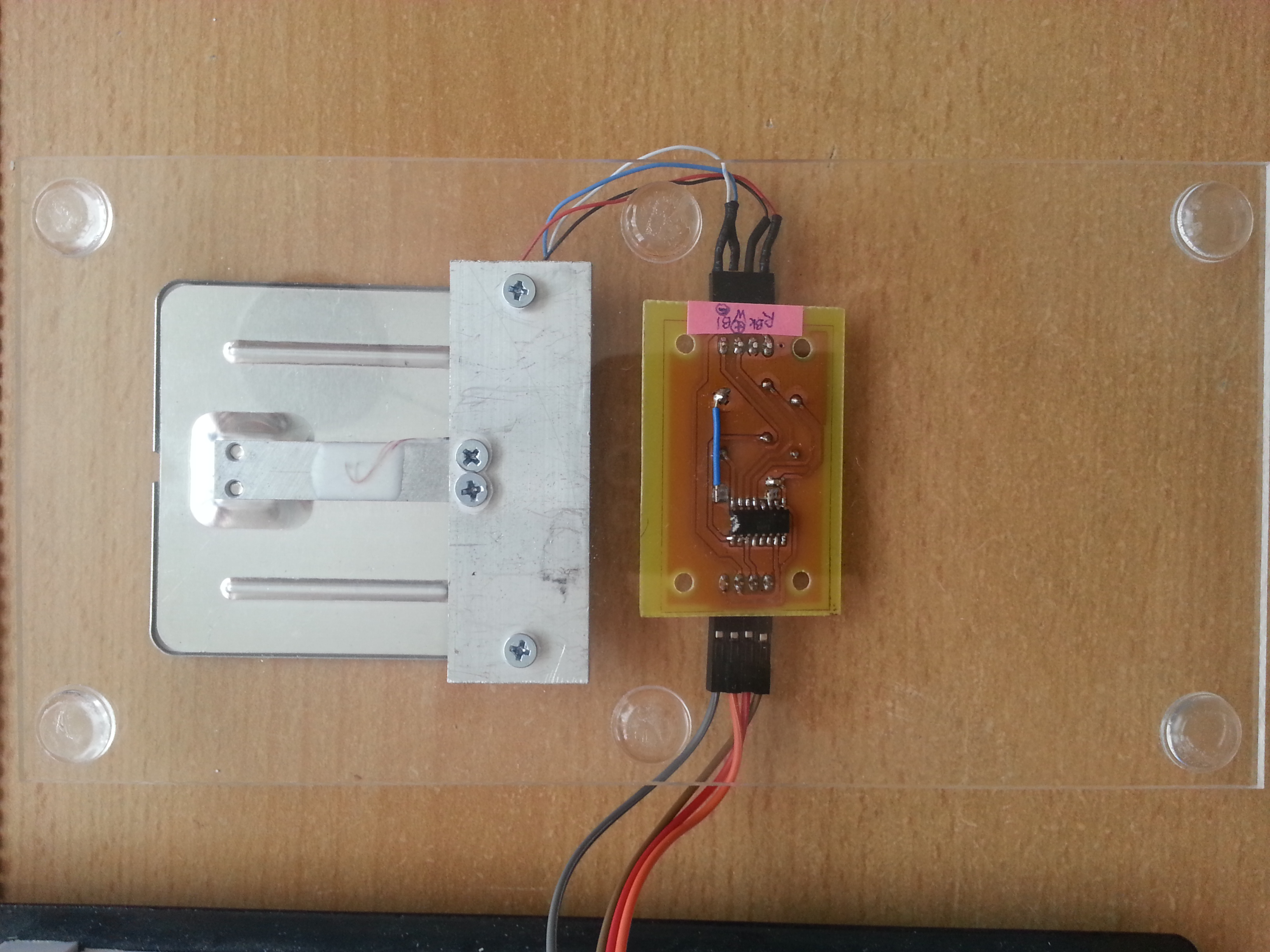
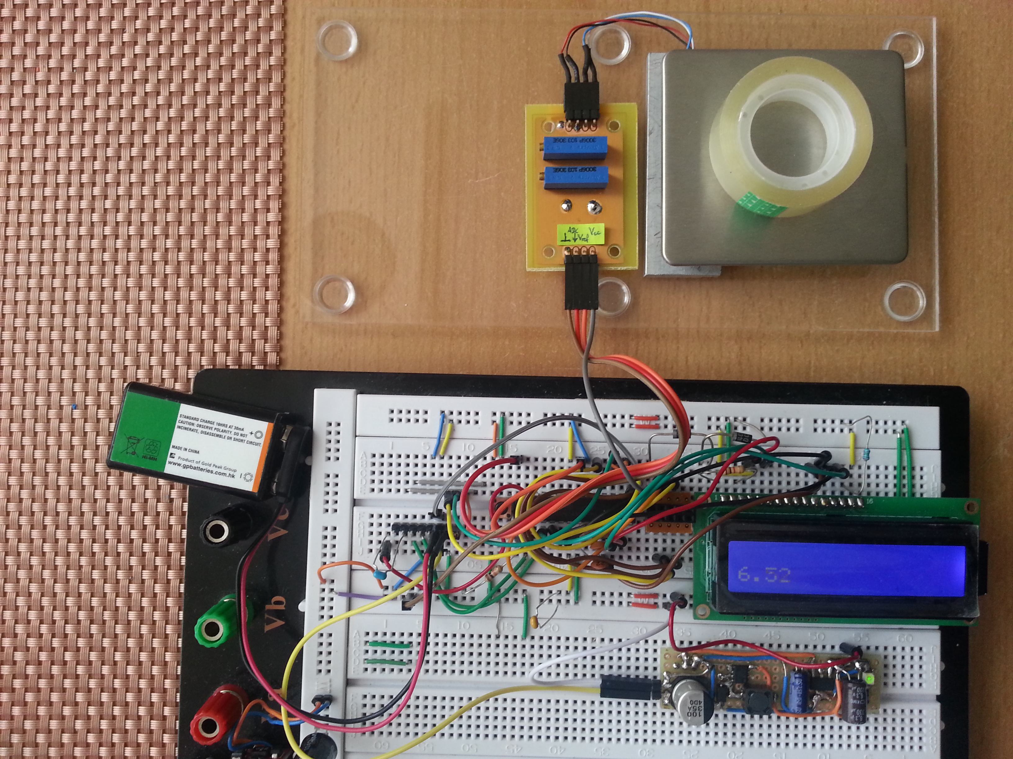
If you are looking for small load cells on ebay or similar shops, you will probably figure out that a cheap mini scales (around 4€) is even cheaper than a single load cell of comparable size (5€). This is why I purchased the complete device rated for up to 1 kg and disassembled it. Prior to taking it apart I measured the weight of some small household items to use them as calibration weights later on in the calibration process. The second advantage you have when getting complete scales is the flat and stable platform mounted on the load cell for you so you don’t have to do it yourself.
Here’s the complete scales on a breadboard. For wiring of the analog part with the microcontroller check the tutorial above.
The load cell was mounted to an acrylic plate with a piece of aluminum in between for stable weight distribution.
Here’s the schematics and the board file for the SMD INA125 (as always in eagle format):
Load Cell Amplifier
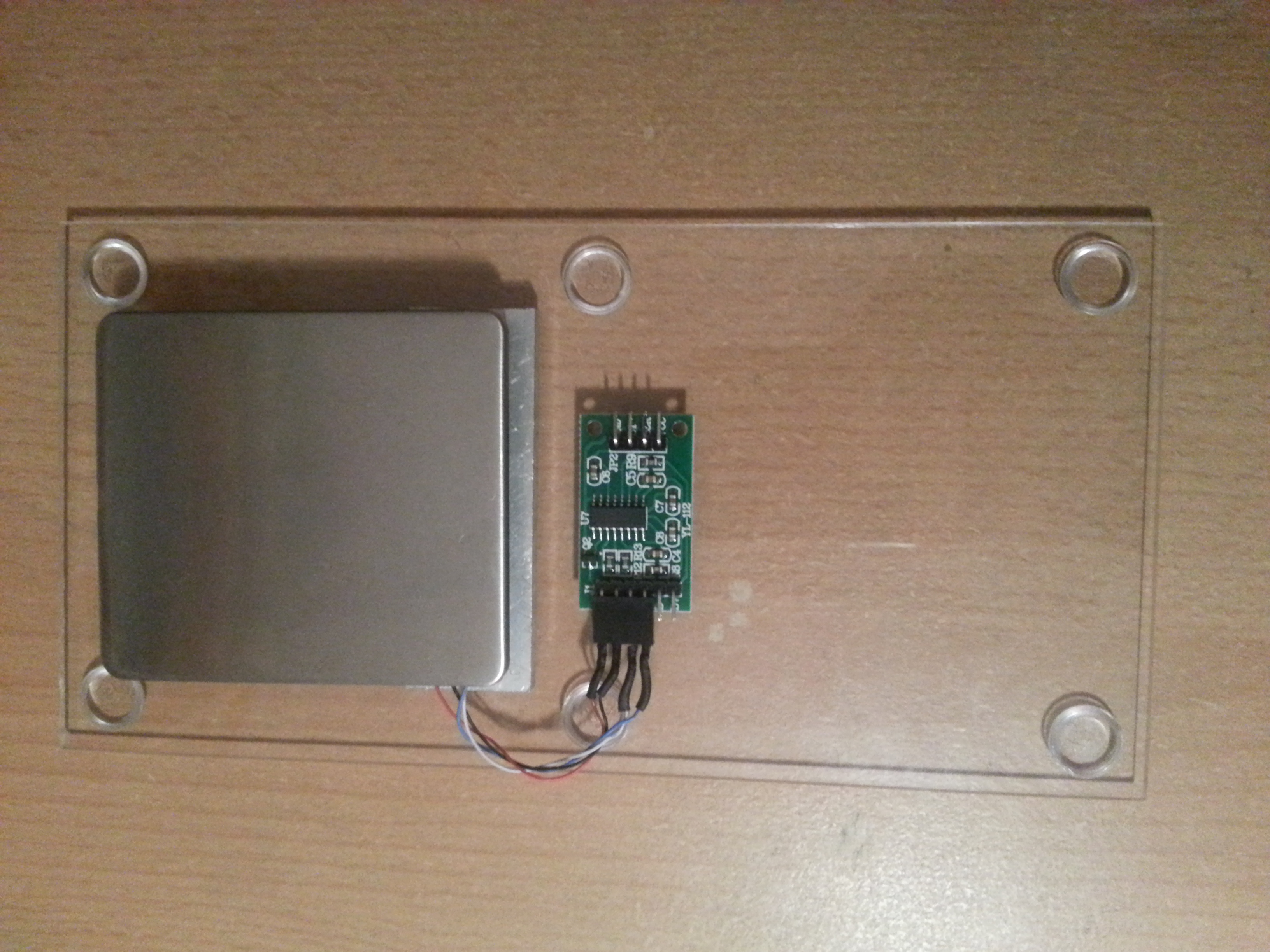
Update: After finding the HX711 breakout board on ebay I upgraded the scales board to this interesting part. It’s a 24 bit ADC that can communicate to a microcontroller over a synchronous serial protocol. It is specifically designed to amplify signals from load cells and gives you a higher resolution (0.1 g). Several Arduino libraries for this chip are around.
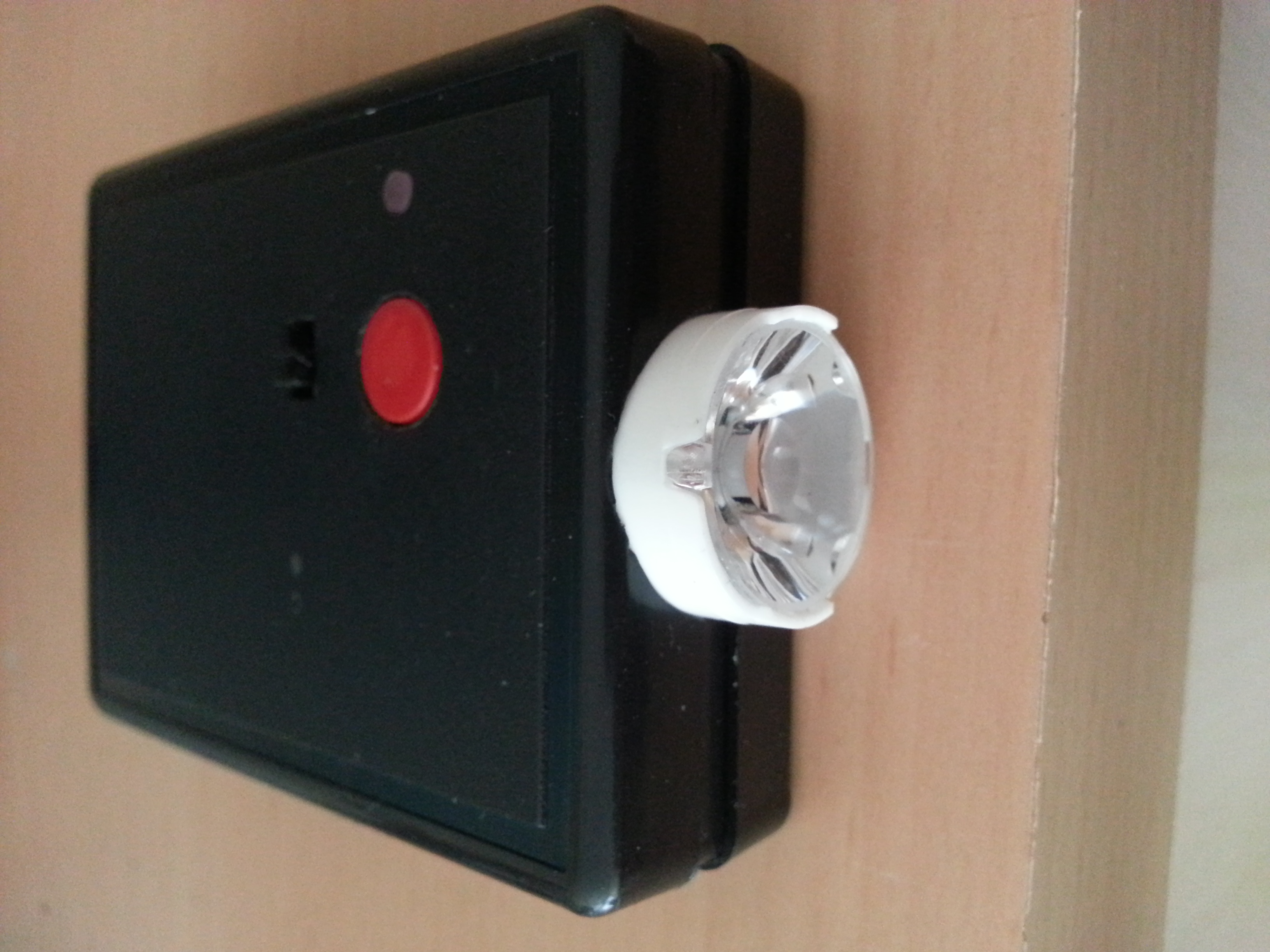
TV-B-Gone Deluxe
TV-B-Gone clone with LiPo battery charger and 1W infrared LED


Arduino-Android Telnet Interface
Arduino-Android CC3000 Wifi chip-based Telnet Interface
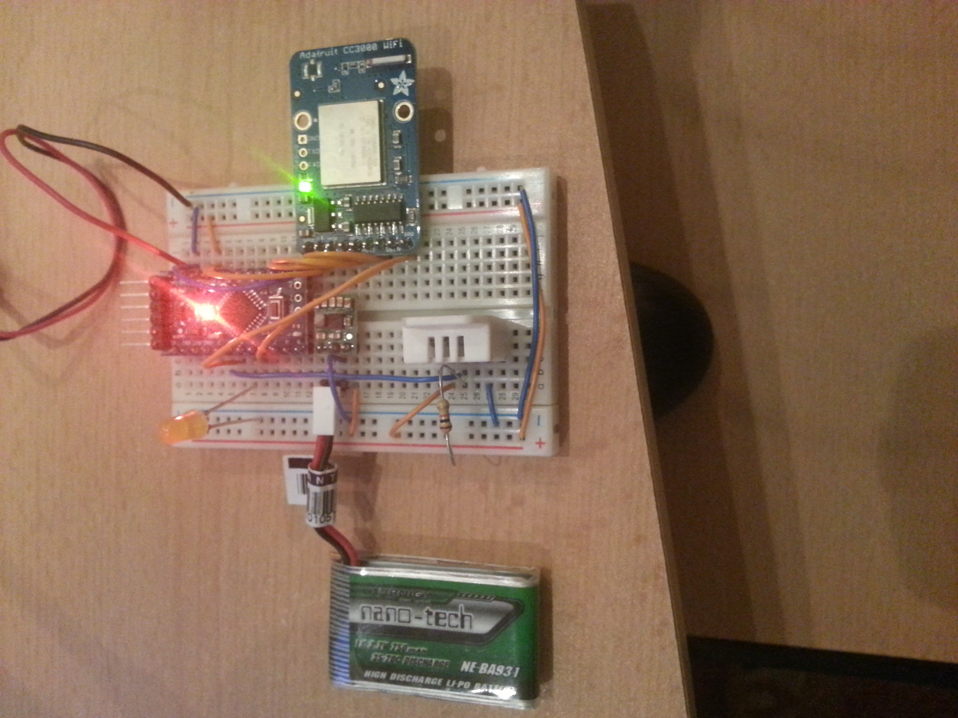
This page provides some guidance on how to set up a wifi connection between an Android device and a minimalistic arduino-based server. The wifi chip used in this project is the CC3000.
Tutorials on how to get the CC3000 to work with the Arduino are all over the WWW, what I would like to add is an example on how to have the Arduino talk to a smartphone or similar.
The communication protocol used here is Telnet. The data comes from a DHT22 sensor which measures humidity and temperature. Actually this is an extended mashup of the open home automation and the candy bowl project. The Android App uses client sockets to communicate to the arduino, which operates in server mode.
Android App Code (ADT Eclipse project):
TelnetClient
Arduino Code:
CC3000_Telnet_server_DHT22
Simple ECG/EEG/EMG amplifier
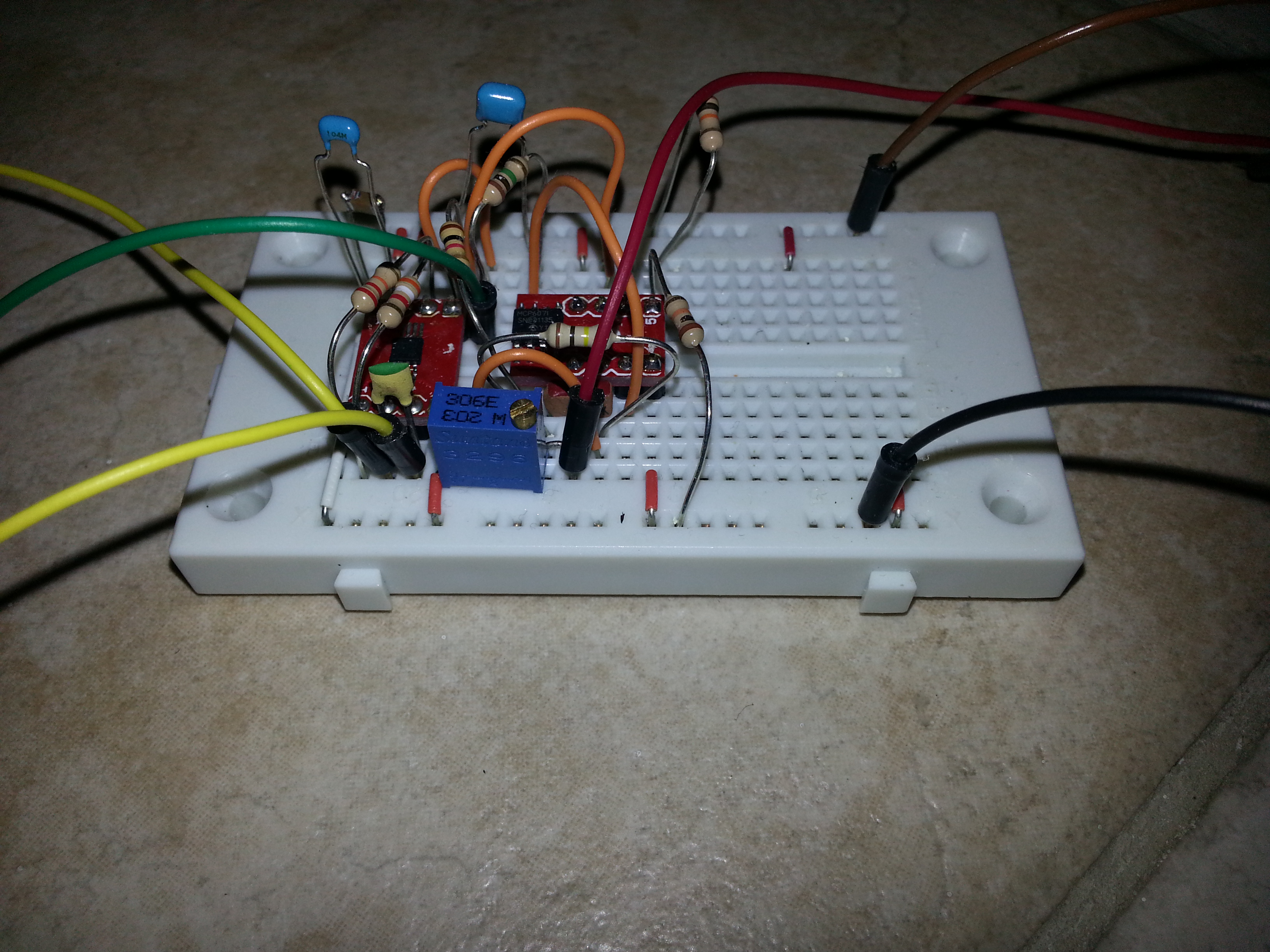
I’ve been experimenting with electrophysiology for some time and therefore the need to better understand the amplifier circuitry arose. I sampled some INA321 instrumentation amplifiers from Texas Instruments and started experimenting. After soldering them to a breakout board you can breadboard them.
The simple setup below can readily be attached to an analog to digital converter of a microcontroller and to 3 skin electrodes wherever you like to attach them 😉
Besides the instrumentation amp (chip on the left) only one additional dual low-noise opamp is used, which implements a buffer for reference voltage and a bessel filter for reducing mains line interference.
Eagle schmatic:
simplestEEG