Category Archives: Arduino/Microcontrollers

builds and hacks including microcontrollers

Jumbo I2C 4-Digit LED Display

This is a huge 4-digit i2c display based on an Atmega8 @16MHz which operates as a i2c slave and does all the multiplexing via timer interrupt. The display is composed of four sa23-12srwa seven segment displays (common anode) with a digit height of 57mm. The firmware for the Atmega8 was written in AVR Studio in C.


It can be addressed simply connecting it to an Arduino and using the wire library. Whenever an ultra-readable bright digit display is needed that is easy to use, this one might come in handy. Some projects I thought of were an oldschool thermometer clock or a distance-measuring device for the garage entrance.


Circuit details Jumbo LED Display


The anodes are driven using an ADN2981 driver and are attached to PB0…3. The cathodes take up the entire PORT D and are driven by a ULN2803. Those drivers are necessary, since the segments (except for the decimal point) are several red LEDs connected in series dropping ca. 7.4V. One does not simply connect one of those to a blank microcontroller port.


I2C Arduino Jumbo LED Display


Source code for the Atmega8 (AVR Studio, C) as well as the Arduino which acts as a I2C master:


I2CjumboDisplayFirmware


// Functions to talk to the DIY jumbo LED four digit display board


#include <Wire.h>

void setup()
{
  Wire.begin(); // join i2c bus (address optional for master)
}


void loop()
{
  for(int i = 0; i < 10000; i++){
    ledDisplayInt(i);
    delay(30);
  }
}

void ledDisplayInt(int number){
  int number_disass = number;
  int Digit_X000, Digit_0X00, Digit_00X0, Digit_000X;
  Digit_X000 = number_disass/1000; 
  number_disass %= 1000;
  Digit_0X00 = number_disass/100;  
  number_disass %= 100;
  Digit_00X0 = number_disass/10;	  
  number_disass %= 10;
  Digit_000X = number_disass;
  Wire.beginTransmission(40); // transmit to device #40 for some reason it addresses a slave with the address 0x50
  //Wire.write("x is ");        // sends five bytes
  Wire.write(byte(0));  //begin
  //sending 0...9 displays the digit, sending 10 makes digit dark
  if(number > 999){
    Wire.write(Digit_X000);              //thousands
  }
  else{
    Wire.write(10);   
  }
  if(number > 99){
    Wire.write(Digit_0X00);                //hundreds
  }
  else{
    Wire.write(10);   
  }
  if(number > 9){
    Wire.write(Digit_00X0);                //tens
  }
  else{
    Wire.write(10);   
  }
  Wire.write(Digit_000X);                //ones
  Wire.write(4);                //decimal point position (0...3, 4 is no comma)
  Wire.write(1);                //display on/off (0x00 => off)
  Wire.endTransmission();    // stop transmitting
}

Arduino “Soundcard”

DAC-Based WAV-Player on a breadboard with MCP4921 and TDA7052


soundcard breadboard


This breadboard assembly is an alternative to the Adafruit Wave Shield, which can read .wav files from an SD card and uses a 12 bit digital to analog converter (MCP4921) with an audio amplifier to give the microcontroller audio output. While building the wave shield on a breadboard I found that the sound quality of used opamp was somewhat poor, so I replaced it with a small audio amp chip. This resulted in better audio quality and higher output power.


arduino soundcard


The schematic is self-explanatory. The design is very simple and can be brought into a breadboard-friendly form factor. For connection details of the SD card check out the wave shield schematic.


Note: I’ve forgotten to include a 10nF low-pass-filter capacitor between the input pin of the TDA7052 and ground. It is not obligatory but removes some noise, so you might try that when replicating this device.

Blood Pressure Monitor Hack

Blood pressure Monitor SBM30 (hl868ba) Arduino hack

In some of my internships in hospital, I was wondering if the Schellong Test could be performed automatically. In order to do that one would have to build a programmable blood pressure measuring device. But wait, can’t we just hack an existing one? I had an SBM30 lying around, which is technically the same as this device. this post by Joe Desbonnet covers the hacking of it. I continued his work. The goal was to make the device completely controllable through its handy testpoint interface. This is what I ended up with:


sbm30 jack


sbm30 ribbon cable


sbm30 testpoints soldered


sbm30+arduino mega 3


/**
SANITAS SBM30 / HL868BA / HL168Y blood pressure monitor hack


 * I2C bus snooper. Written to eavesdrop on MCU to EEPROM 
 * communications in a HL168Y blood pressure monitor. SCL 
 * is connected to Arduino pin 2 and SDA to pin 3 (UNO).
 * This version will decode read and write operations to 
 * EEPROM outputting heart rate and blood pressure to the serial port 

 * Adapted to ARDUINO UNO: PIND2: D2 -> SCL of EEPROM; PIND3: D3 -> SDA of EEPROM
 
 */
 
//watchdog timer include 
#include <avr/wdt.h> 

//////////////////////////////////////////////////////////////////////////////////////////////////////////////////
//pins to connect the the data and clock line to. 
//PORTD 2 & 3 on the UNO: use digital pins 2 and 3
//digital pins 18 and 19 are PORTD 2 & 3 on the Arduino Mega, so you need to change Sclock to 18 and Sdata to 19
//any GPIO pins can be chosen, but the direct port manipulations in the takeMeasurement() function have to be changed!!
int Sclock = 2;
int Sdata = 3;

//the pin to drive the on/off/start button of the device
int startPin = 12; //attach pin 12 to the field of the start button or the according test point!
int buttonPin = 4; //attach a pushbutton from pin 4 to GND, pressing it will start the measurement and print values to serial monitor (11200 baud)

//////////////////////////////////////////////////////////////////////////////////////////////////////////////////


char hexval[16] = {'0', '1', '2', '3', '4', '5', '6', '7', '8', '9', 'A', 'B', 'C', 'D', 'E', 'F'};

#define LOG_SIZE 255
unsigned char datalog[LOG_SIZE];
unsigned char logptr;
//stores the amount of etracted R aaa vv\n lines after each blood pressure measurement
unsigned char bytesOfData = 0;
boolean measuring_now = false;
boolean measuring_failed = false;

//bytes to store the final and most important values
unsigned char heart_rate = 0;
unsigned char diast_press = 0;
unsigned char syst_press = 0;

unsigned char diast_press_hunderter = 0;
unsigned char diast_press_zehner = 0;
unsigned char syst_press_hunderter = 0;
unsigned char syst_press_zehner = 0;


//******************************************************************************************************************************************
//                                                  SETUP and LOOP
//******************************************************************************************************************************************

void setup()   {                
  pinMode(Sclock, INPUT);  
  pinMode(Sdata, INPUT); 
  pinMode(startPin, OUTPUT); 
  pinMode(buttonPin, INPUT); 
  digitalWrite(startPin, HIGH);  //HIGH = not pressed
  digitalWrite(buttonPin, HIGH);
  Serial.begin(115200);

}

void loop()                     
{
 
    if (digitalRead(buttonPin)==LOW)  // Button pressed
    {
      //send signal to BPM
      startButtonActivate();
      //set flag that measurment is running
      //used for breaking out of the waiting loops in the takeMeasurement() function
      measuring_now = true;
    
      takeMeasurement();
    }

  
  //wdt_reset();

}
//******************************************************************************************************************************************
//                                                  FUNCTION DEFINITIONS
//******************************************************************************************************************************************

//Algorithm to passively sniff into the MCU-EEPROM i2c communication of the SBM-30 blood pressure monitor
//based on the code by Joe Desbonnet ( http://jdesbonnet.blogspot.de/2010/05/using-arduino-as-simple-logic-analyzer.html )
void takeMeasurement(){
  
  unsigned char s, b, byteCounter, bitCounter, rwFlag;
  unsigned char addr_hi, addr_lo;
  unsigned int t = 0;
  
  logptr = 0;
  
  waitForStart:

 
   // Expect both SLC and SDA to be high
  while ( (PIND & 0b00001100) != 0b00001100) {

    }
  // both SLC and SDA high at this point
  
  // Looking for START condition. Ie SDA transitioning from 
  // high to low while SLC is high.
  while ( (PIND & 0b00001100) != 0b00000100) {
    //break out of an infinite loop after a measurement! HERE!
    if(measuring_now == false)
      return;

      
    if ( (--t == 0) &&  (logptr > 0) ) {   
        writeData();
    }
  }
  
  firstBit:

      
  byteCounter = 0;
  bitCounter = 0;
  
  nextBit:

  // If SCL high, wait for SCL low
  while ( (PIND & 0b00000100) != 0) {

    }
    
  // Wait for SCL to transition high. Nothing of interest happens when SCL is low.
  while ( (PIND & 0b00000100) == 0) {

    }
    
  // Sample SDA at the SCL low->high transition point. Don't know yet if this is a
  // data bit or a STOP or START condition.
  s = PIND & 0b00001000;
    
  // Wait for SCL to transition low while monitoring SDA for a transition.
  // No transition means we have data or ACK bit (sample in 's'). A hight to
  // low SDA = START, a low to high SDA transition = STOP.
  if (s == 0) {
    // loop while SCL high and SDA low
    while ( (PIND & 0b00001100) == 0b00000100) {

    }
    if ( (PIND & 0b00001100) == 0b00001100) {
         // STOP condition detected
         if (logptr > LOG_SIZE - 20) {
        
           writeData();
         }
         goto waitForStart;
    }
  } else {
    // loop while SCL high and SDA high
    while ( (PIND & 0b00001100) == 0b00001100) {

    }
    if ( (PIND & 0b00001100) == 0b00000100) {
        // START condition.
        goto firstBit;
    }
  }
  
  // OK. This is a data bit.
  bitCounter++;
  
  if (bitCounter < 9) {    
    b <<= 1;
    // if data bit is '1' set it in LSB position (will default to 0 after the shift op)
    if (s != 0) {
      b |= 0b00000001;
    }
    
    goto nextBit;
  }
  
  // 9th bit (ack/noack)
  
  bitCounter = 0;
  byteCounter++;
  
  switch (byteCounter) {
    case 1: // 1010AAAW where AAA upper 3 bits of address, W = 0 for writer, 1 for read
    if ( (b & 0b11110000) != 0b10100000) {
      goto waitForStart;
    }
    // Set A9,A8 bits of address
    addr_hi = (b>>1) & 0b00000011;
    rwFlag = b & 0b00000001;
    break;
    
    case 2: // data if rwFlag==1 else lower 8 bits of address
    if (rwFlag == 1) {
      // data read from eeprom. Expect this to be the last byte before P
      //datalog[logptr++] = ' ';
      datalog[logptr++] = 'R';
      datalog[logptr++] = ' ';
      datalog[logptr++] = hexval[addr_hi];
      datalog[logptr++] = hexval[addr_lo>>4];
      datalog[logptr++] = hexval[addr_lo & 0b00001111];
      datalog[logptr++] = ' ';
      datalog[logptr++] = hexval[b >> 4];
      datalog[logptr++] = hexval[b & 0b00001111];
      datalog[logptr++] = '\n';
    } else {
      addr_lo = b;
    }
    break;
   
    case 3: // only have 3rd byte if rwFlag==0. This will be the data.
    if (rwFlag == 0) {
      //datalog[logptr++] = ' ';
      datalog[logptr++] = 'W';
      datalog[logptr++] = ' ';
      datalog[logptr++] = hexval[addr_hi];
      datalog[logptr++] = hexval[addr_lo>>4];
      datalog[logptr++] = hexval[addr_lo & 0b00001111];
      datalog[logptr++] = ' ';
      datalog[logptr++] = hexval[b>>4];
      datalog[logptr++] = hexval[b & 0b00001111];
      datalog[logptr++] = '\n';

      if (logptr > LOG_SIZE - 10) {
        writeData();
      }
      
      break;
    }
    
  } // end switch
 
  goto nextBit;
}

//******************************************************************************************************************************************

//start working with the lines (= "important data bytes") that are written to the EEPROM after a measurement was taken!
void writeData () {
  //we only need the data that is "written" , in particular the heart rate and blood pressure, which are two chars that encode hex numbers
  if(datalog[0]=='W'){
     //sometimes two lines are extracted at once, here the data extraction is done and the calculateValues function is called with the values
      if(logptr > 10){
        calculateValues(datalog[6], datalog[7]);
        bytesOfData++;
        
        calculateValues(datalog[15], datalog[16]);
        bytesOfData++;
      } else {
        //when only one line (= "important data byte") is extracted from the eeprom write procedure after the measurement
        calculateValues(datalog[6], datalog[7]);
        bytesOfData++;
      }
       
    }
    
   measuring_failed = false; //if that comes after 
   //device reads from eeprom when you start measuring, so reset the counter for the most important "data bytes"
   if(datalog[0]=='R'){
     bytesOfData = 0;
   }else if(bytesOfData > 9){
     bytesOfData = 0;
     writeToSerial();
   }/*else if(bytesOfData >= 8){  //this means that a measurement has failed
     wdt_enable(WDTO_4S);                //WATCHDOG!! if no data is written to the screen, because only 9 bytes are extracted (sometimes fucking happens)
     measuring_failed = true;
   }*/
  
  //clear datalog[] and logptr  
  for (int i = 0; i < logptr; i++) {
    //Serial.write(datalog[i]); //use Serial.write() to send BYTES!!!!!!!!!   
    datalog[i] = 0;
  }
  //Serial.println(logptr);
  logptr=0; 
  //Serial.write('\n');
}

//******************************************************************************************************************************************

//make hex numbers out of ASCII characters
byte getVal(char c)
{
 if(c >= '0' && c <= '9')
   return (byte)(c - '0');
 else
   return (byte)(c-'A'+10);
}
//******************************************************************************************************************************************

//LCD display function, prints out the new values
//gets called at the very end of the measurement and data acquisition process
void writeToSerial(){
 
  
  Serial.print("heart rate: ");
  Serial.println(heart_rate);
  
  Serial.print("pressure: ");
  Serial.print(syst_press);
  Serial.print("/");
  Serial.println(diast_press);
  //once written, you can continue doing other stuff
  
  measuring_now = false;
  
}

//******************************************************************************************************************************************

//calculates HR from HEX number and decodes the syst. and diast. blood pressure values from line 5-7
void calculateValues(char char6, char char7){
  if( bytesOfData == 9){
    //calculate the pressures 
    syst_press = syst_press_hunderter + syst_press_zehner;
    diast_press = diast_press_hunderter + diast_press_zehner;

  }
  if( bytesOfData == 8){
    //heart rate is encoded in two hex chars
    //make a byte out of two nibbles
    heart_rate = getVal(char7) + (getVal(char6) << 4);
    
  }
  //diastolic value last two digits
  if( bytesOfData == 7){
    diast_press_zehner = (char6 - '0') * 10 +  (char7 - '0');
  }
  //systolic value last two digits
  if( bytesOfData == 6){
    syst_press_zehner = (char6 - '0') * 10 +  (char7 - '0');
  }
  //diastolic and systolic value first digit
  if( bytesOfData == 5){
    diast_press_hunderter = (char7 - '0') * 100;
    syst_press_hunderter = (char6 - '0') * 100;
  }
          
}

//******************************************************************************************************************************************

//Sequence of pulling the test point of the SBM-30 low twice to turn on and/or make the device start measuring

void startButtonActivate(){
    digitalWrite(startPin, LOW);
    delay(100);
    digitalWrite(startPin, HIGH);
    delay(400);
    digitalWrite(startPin, LOW);
    delay(100);
    digitalWrite(startPin, HIGH);
}

Raspberry Pi Hacktop

Raspberry Pi Hacktop – a convenient development environment for the RPi

When experimenting with the Raspberry Pi one wishes to have the essential stuff handy: a breadboard, a USB hub, a speaker, a (debug) monitor, keyboard and mouse, WiFi, different supply voltages, and maybe even battery power. An ON/OFF switch would be nice as well.

So why bother: simply attach all the stuff you need to a compact piece of plywood. The 5V for the Pi are supplied by a buck regulator (max. 3A ), whose input voltage goes directly to the mini AV-mini monitor, which makes a sufficient and cheap screen for many purposes, when you adapt the resolution to make things readable. A separate linear regulator makes 3,3V @ 1A on the other breadboard rail in case you need them. Now you can use power supplies and batteries over a wide voltage range (I think the monitor as well as the LM2596 can take quite high input voltages, even above 15V).

Now you have everything handy, you can develop your RPi projects without having severe chaos on your desktop…

Raspberry Pi Hacktop

RPi Hacktop with Keyboard

Intro to NXP Microcontrollers and mbed

Simple ways to start developing on ARM Cortex Microcontrollers


Out of curiosity and because ARM-based MCUs are becoming cheaper and even less power-consuming than AVR chips while offering way more processing power, I have considered to give it a trial.


Inspired by projects like anykey or the awesome code bases by microbuilder I’ve decided to choose NXP chips.


The LPC1343 (Cortex M3) is the main chip I’m working with at the moment, since the microbuilder code base is really versatile. An affordable small board called the Quick Start Board is available from Embedded Artist, which makes it easy to program that chip via different interfaces. A very interesting one is the USB bootloader, which makes the device appear as a mass storage device and enables you to simply drag in the firmware without the need for an external programmer. The Quick Start Board also has a 10 pin jtag connector, which can be connected to the LPC-Link, a jtag debugger that is integrated into the LPCxpresso boards. Some other things that are on board are a i2c EEPROM (LPC1343 lacks EEPROM), a 5V->3V3 regulator, bootloader and reset button and an LED on PIO0_7.


20130207_133520


NXP also produces the LPC1114FN28, which is the only ARM- based microcontroller in a DIP package. It’s cheap and perfect for quick DIY applications. I got 2 of them from ebay just for kicks. All you need to get started is an FTDI breakout board, a couple of standard discrete components, and a code base. On the picture above, on the second half of the breadboard you can see that minimal setup with room to plug ion the FTDI board on the right. When the resistor that is floating in the air is connected to GND and the device is reset, it enters the UART bootloader mode.


Since microbuilder is about to release a code base for the LPC1347, which has 64k flash size, 12bit ADCs, buil-in EEPROM and stuff, the LPCxpresso board I ordered had the LPC1347 target. I cut it in half right away to use the LPC-Link half for the LPC1343. The LPC1347 target portion was hacked and saved for use in future projects. I added a pulldown button to PIO0_0 (RESET) and one to PIO0_1 (USB bootloader mode, just like on the LPC1343) as well as a LM 3940 IMP-3,3 voltage regulator for getting power from the USB port.


A small step for mankind, but a somewhat bigger step for me. I discovered that the mbed platform supports the LPC1114FN28 as well as the LPC1347! Mbed is an ARM development platform with an online compiler and a greatly interconnected community with unique opportunities to share projects. One can simply browse what other people have written and use and contribute. When you compile your browser spits out a xxxxxx.bin file that you can rename to firmware.bin and load into the LPC1347 mass storage bootloader. The LPC1114FN28 breadboard platform as seen above can be used with Flash Magic, but you need a bin to hex converter. Everything is explained under the platforms section.


20130207_134544


Conclusion


The NXP LPCs seem to be a good platform to start from if you would like to migrate to ARM or a 32bit platform. I thought it might also be a good opportunity to familiarize oneself with the jtag hardware debugging concept, which you do not encounter if you stick to Arduino alone. Of course there is the question,how big the user community is / will be, since sharing code is quite important, but on the other hand: ARM processors are more fluid in executing C code and handling 32bit integers, so if you have a code base such as the one that is available from microbuilder, you should be able to accomplish quite a bit. Microbuilder has also got a great forum where you are really helped out if you have any issues.


The possibility to use the mbed copiler for the LPC1347 and the LPC1114FN28 opens some great opportunities for ARM-based projects. Its simplicity of use should make tinkering with ARM chips much easier.


One way to start: the LPC1114FN28 can be programmed using the Seeeduino Arch (a quite cheap arduino-shaped LPC11U24 board) as a SWD programmer to drag in .bin files from the mbed compiler. Check out this mbed page.


20140606_185414


I found the LPC1114FN28 very useful and so it was made Arduino-compatible by soldering it on a proto shield PCB and breakung out all the pins that are protocol-compatible. For example ADC-pins (The LPC1114FN28 only has 5 of them), SPI, I2C and UART are pin compatible now. As a power supply almost any battery can be connected (2-11 V), since an efficient 5V pololu boost/buck switching regulator is soldered onto the board. A 3.3V LDO linear regulator supplies the microcontroller.

Bluetooth Message Receiver

I like developing Arduino projects without the usual hardware, by simply using the bare minimum that’s necessary. It’s really cheap, it can have very small dimensions and be embedded almost anywhere. You are flexible with power supplies and logic levels as well. Here is one example: simply put a Atmega 328 with UNO bootloader on a breadboard, power it up with 3.3V and you can connect efficient and cheap 3.3V components to it such as bluetooth modules and OLED displays. As you can see, the power source is a Sparkfun 3.3V step-up board, so that the whole setup can run from a single AA cell. A standard 6-pin header for the usual FTDI breakout boards is also built in.


Bluetooth connectivity is given by connecting a HC-05 master/slave BT-module. This thing can also be easily breadboarded if you solder wires only to the necessary terminals. For pinout and AT command set (for adjusting the baud rate etc.) click. There are several modules out there that look alike (the HC-06 for example), but run different firmwares and therefore different AT command sets, so watch out for that.


20121125_181420


The OLED display used here has only 0.96” screen diagonal, but 128×64 pixels and a very high contrast. It can display a lot of information on a small area. When using the fonts from Ladyada’s libraries (see below) you can display 8×21 characters with the small font or 4×10 characters with the big font.


When communicating over 4-pin SPI you only need 7 pins in total, unlike the 20-pin KS0108 GLCD. Some SMT jumper settings have to be made for the device to operate in 4-wire SPI mode, which can be accomplished with average soldering skills. It’s pretty much self-explanatory and depicted on the PCB if you use the same device as I did. If you build the proper adapter, the display can be plugged directly next to the atmega 328 on a breadboard without using a single jumper wire (i used the pinout from the library!) for very quick and efficient prototyping.


Adafruits OLED and GFX libraries provide a great code base for the built-in SD1306 controller. Their boards have only the relevant pins broken out and the SPI-mode pre-selected for those who don’t like soldering.


20121125_181229

Ballistic Chronograph

Projectile velocity meter based on the Atmega8. It’s still in the breadboard stage of development, but is working already. I’m going to use it to measure the velocities of the coilgun projectiles to determine muzzle energy and efficiency.


The Software was written in BASCOM basic, since this was the platform I started programming microcontrollers. The cheap 2×8 character LCD is connected to PORTB. The INT0 and INT1 pins have a BPW40 phototransistor (positioned 10cm apart from each other) and a 4.7K pullup-resistor connected to each of them.


As long as the light beam hits the phototransistor, it pulls the pin to ground. If the beam is broken, its resistance rises and we’ve got our rising edge on the interrupt pin. INT0 starts the Timer, INT0 stops it. A simple calculation is performed and we’ve got our velocity in [m/s].


velocity meter on breadboard


This side-project was taken as an opportunity to make a PCB with Eagle CAD and the photoresist method. I’ve been making my own PCBs at school, but that was some time ago.


Also, the code was completely rewritten in C using AVR Studio 4.


Below you see my experimental etching setup. A water bath heats up the sodium persulfate to up to 50°C and the aquarium air pump creates some bubbles for movement of the solution around the PCB.


The stencil for developing the PCB was printed on inkjet overhead projector transparencies. 3 stencils were printed and superposed to make the traces more solid. My conclusion is that you don’t reach a resolution high enough for SMD components, at least not with my printer.


etching setup


The final result: The finest component is the ribbon cable connestor for the LCD, a custom eagle part was created for it.


etched PCB for chrono


The brackets for the light barriers were milled using a Proxxon BFB2000-SI-BFW 40/E-SI-KT 150 setup. The IR LEDs and photodiodes were scavenged from some old device.


chrono parts


The final PCB: coated and soldered.


covered PCB for chrono


The final assembly: the light barriers are 30cm apart.


final assembly chrono


Despite having learned a lot during developing this machine, I would consier the end result to be a typical maker FAIL, since this is a very inaccurate instrument. I should find out why this is so some day. Whether it is the source code or the physical assembly…


But I don’t regret a thing! It was a great motivation to acquire some very useful skills!


The Code, as well as the eagle files are found under the link below.


Chronograph

Arduino 7×20 LED Matrix Marquee

with serial interface and therefore Bluetooth capability 🙂


The circuit diagram for the Marquee can be found here
I’ve adapted some Arduino code discussed in the forum (see code below) to work with this device and added a serial interface. The rows are adressed directly via a ULN2003 chip and the colums are adressed through 74HC595 shift registers. The code multiplexes the rows and therefore has less flickering. The device uses a total of 10 microcontroller pins (1 per row and 3 for all the shift registers).


Here’s the project in its compact version with an Atmega328 (arduino bootloader) and a 5V Voltage regulator.


matrixboard

Tracked Robotic Vehicle

Specs:


Tamya dual motor gear box
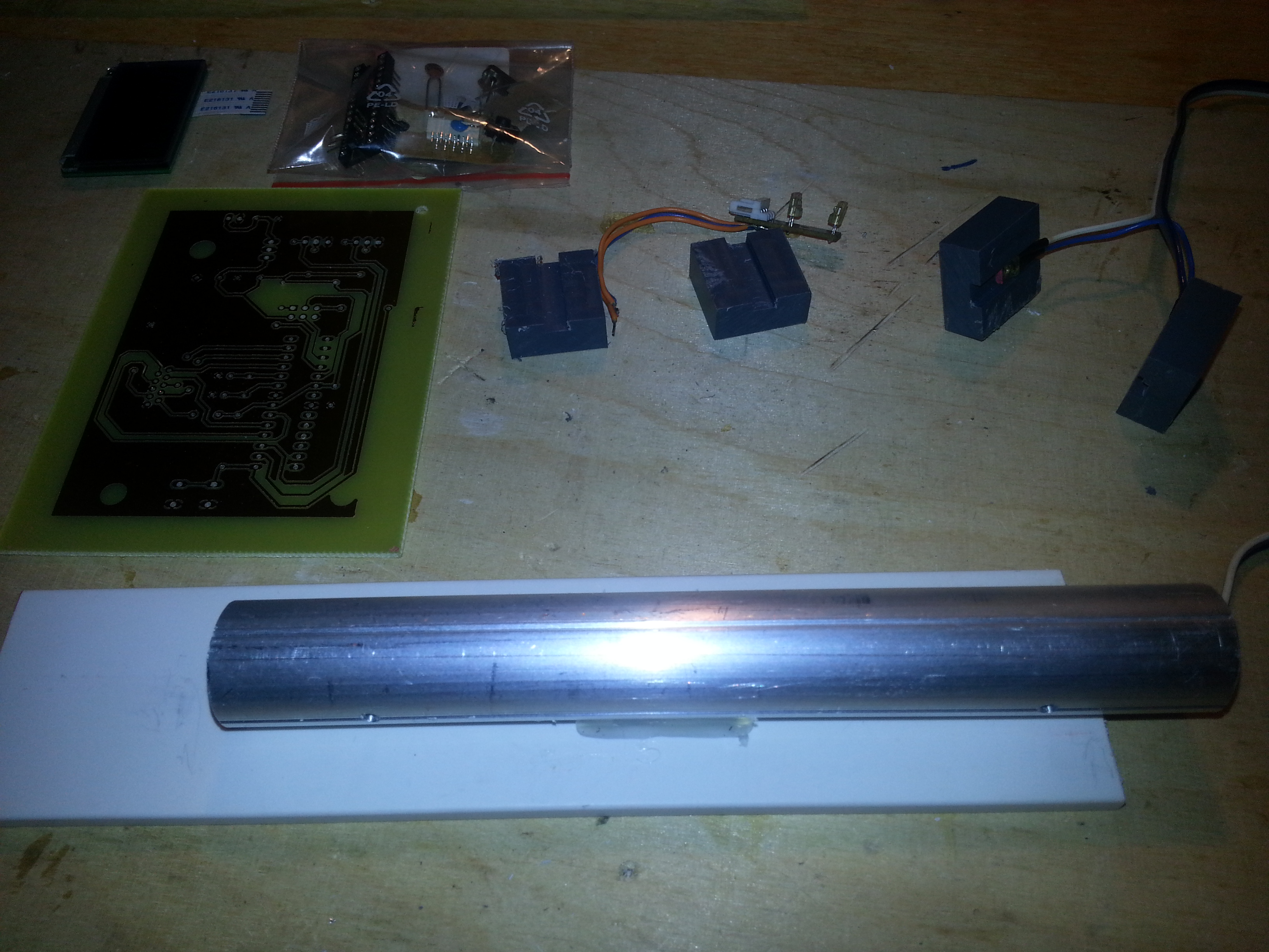
dual homebrew relay-based H-Bridge
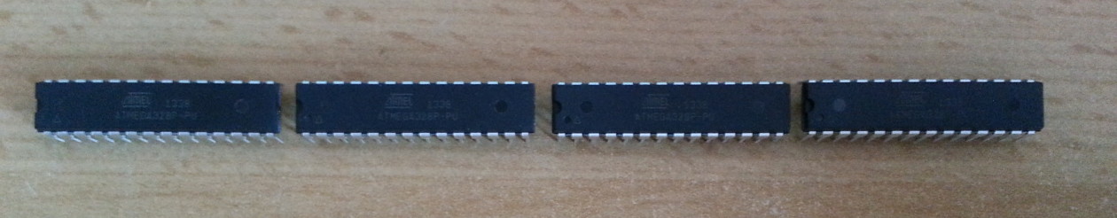
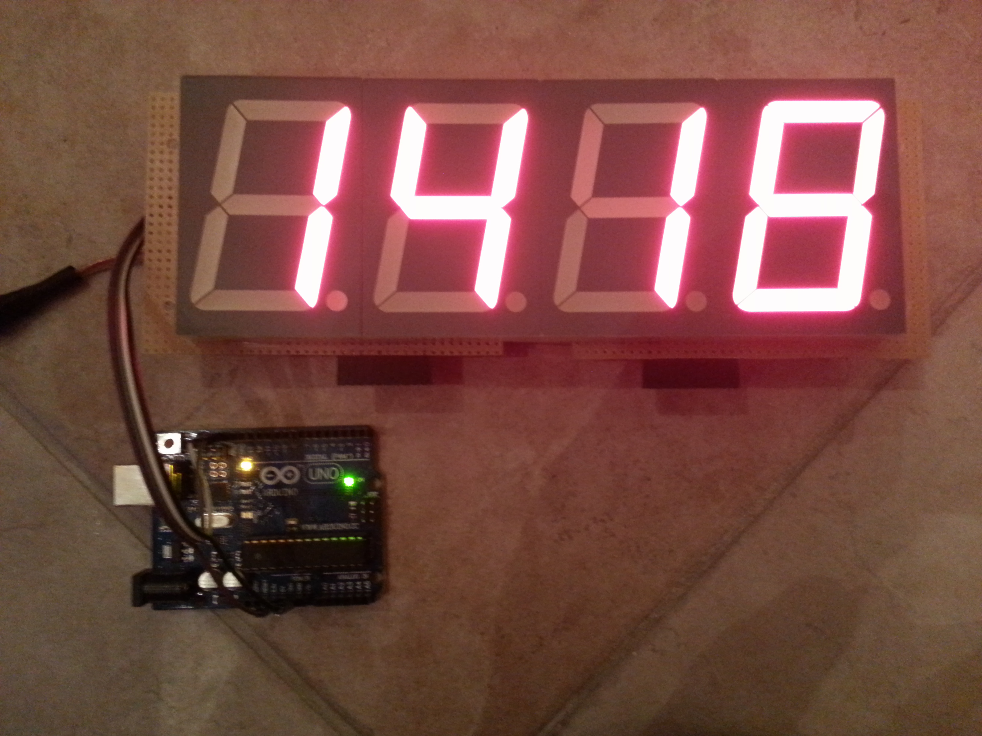
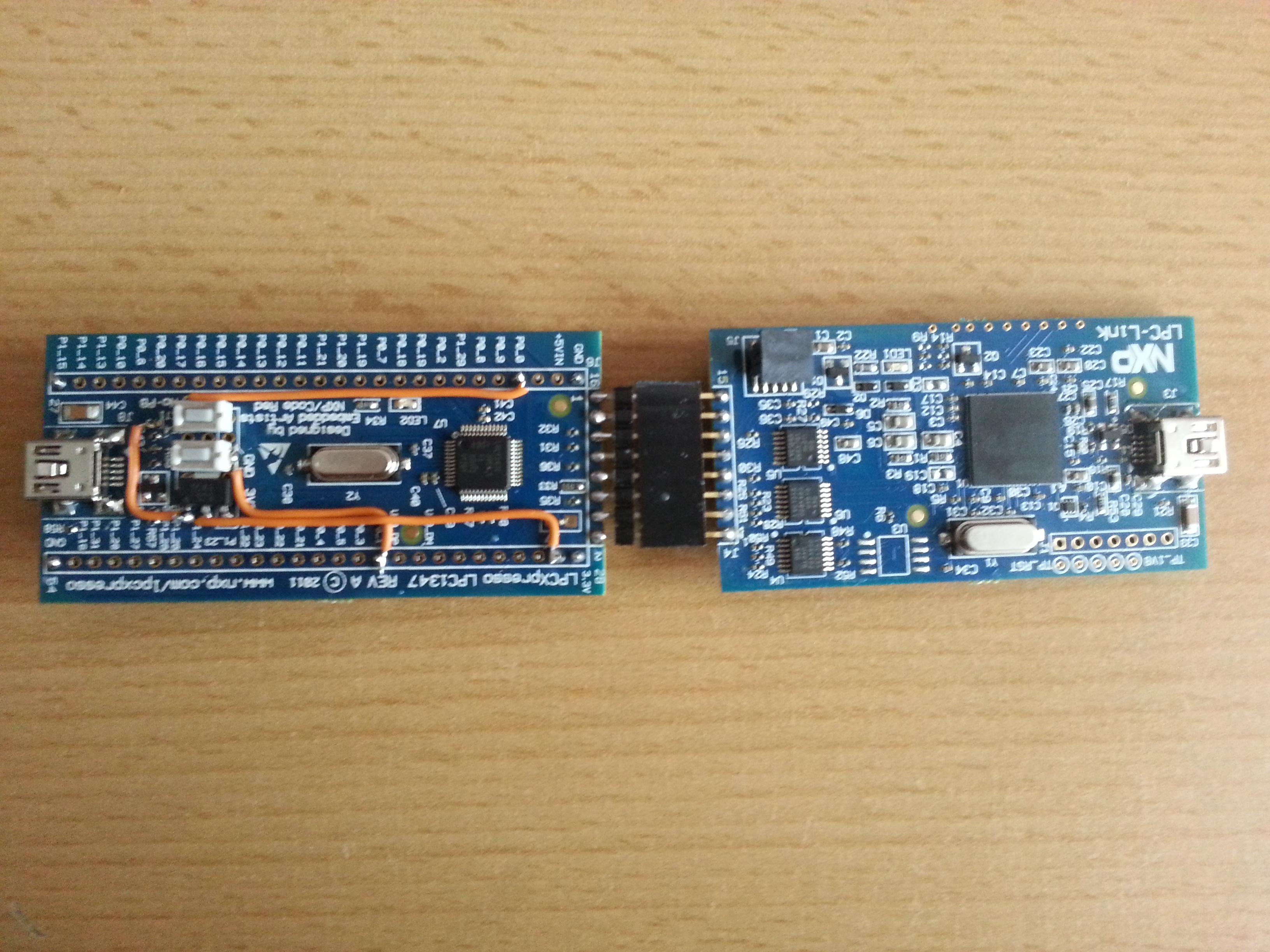
controlled by a Atmega328p with Arduino UNO Bootloader.
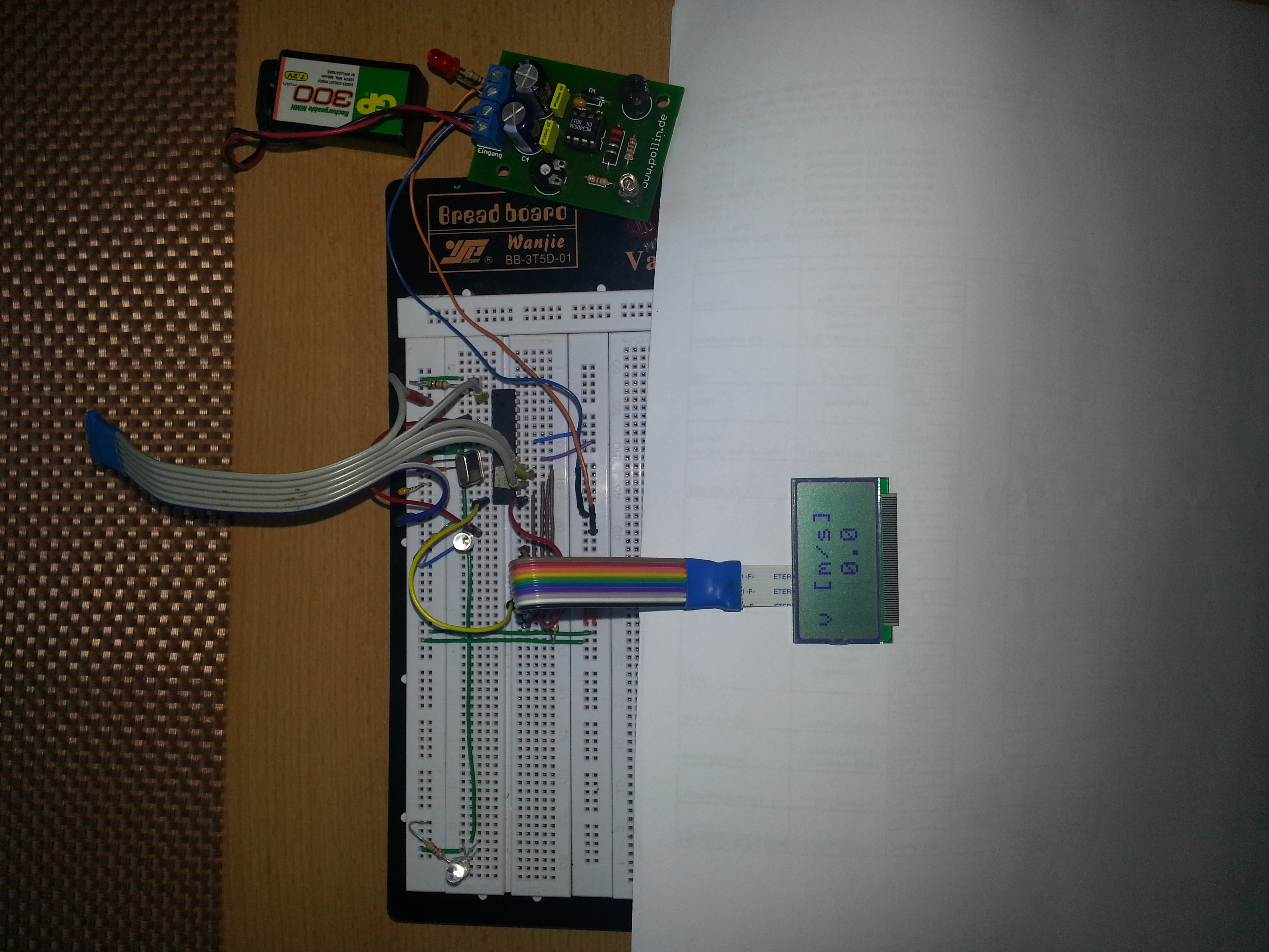
Sharp GP2D120XJ00F distance sensor (range: 10-80cm)
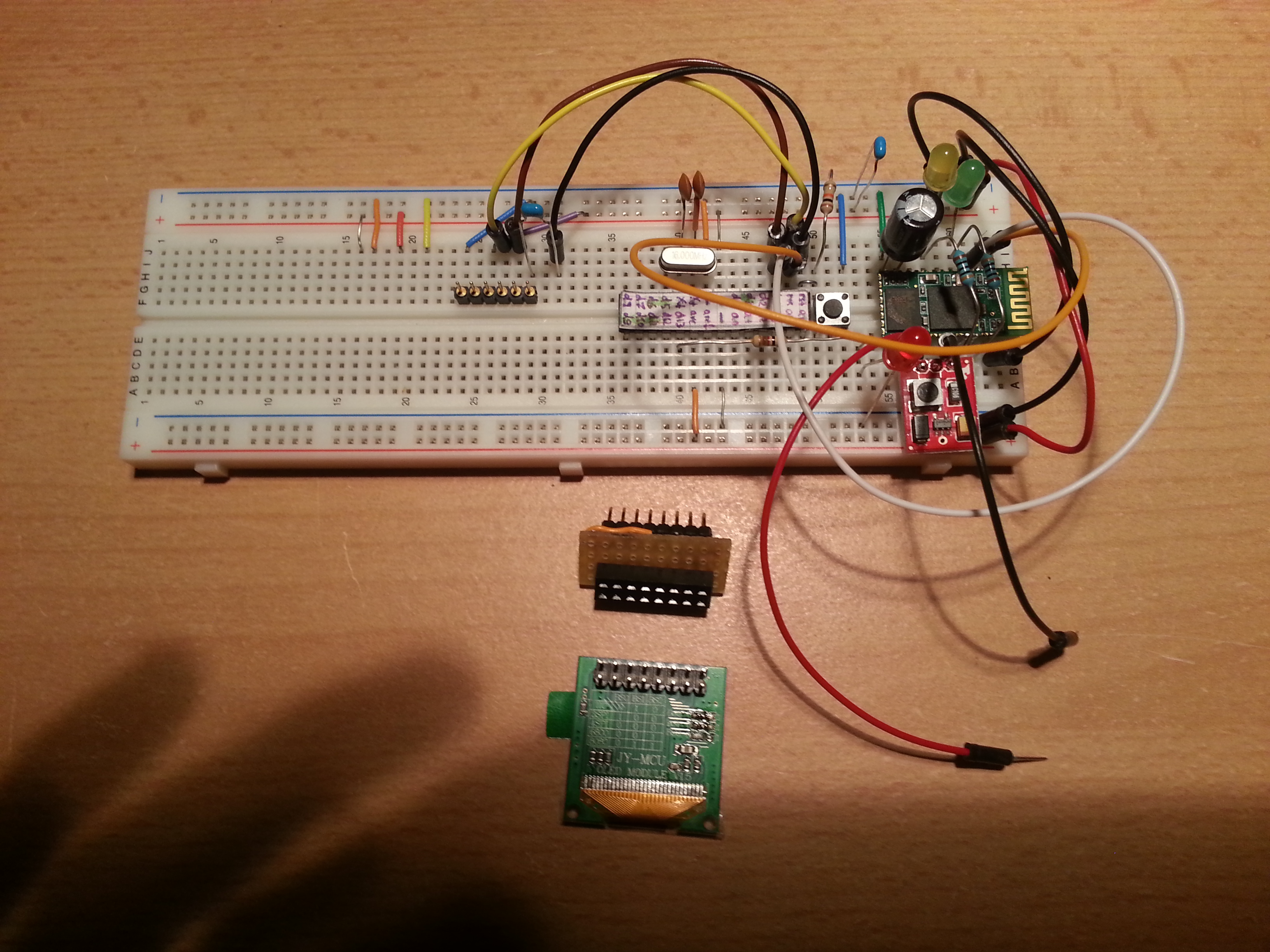
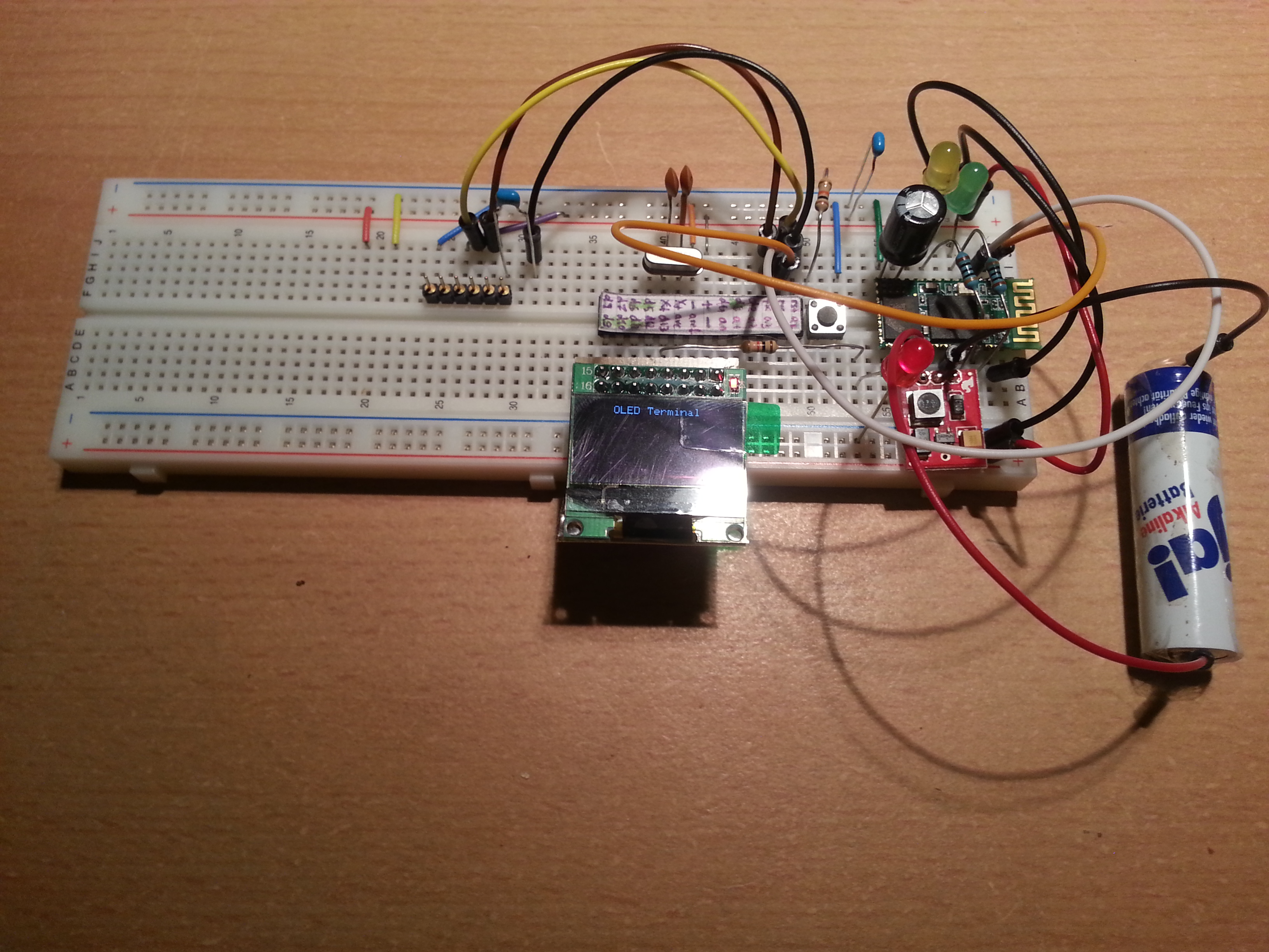
el-cheapo Bluetooth module (HC-06)/Xbee Series 2 modules


20121029_123835


20120803_000750


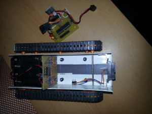
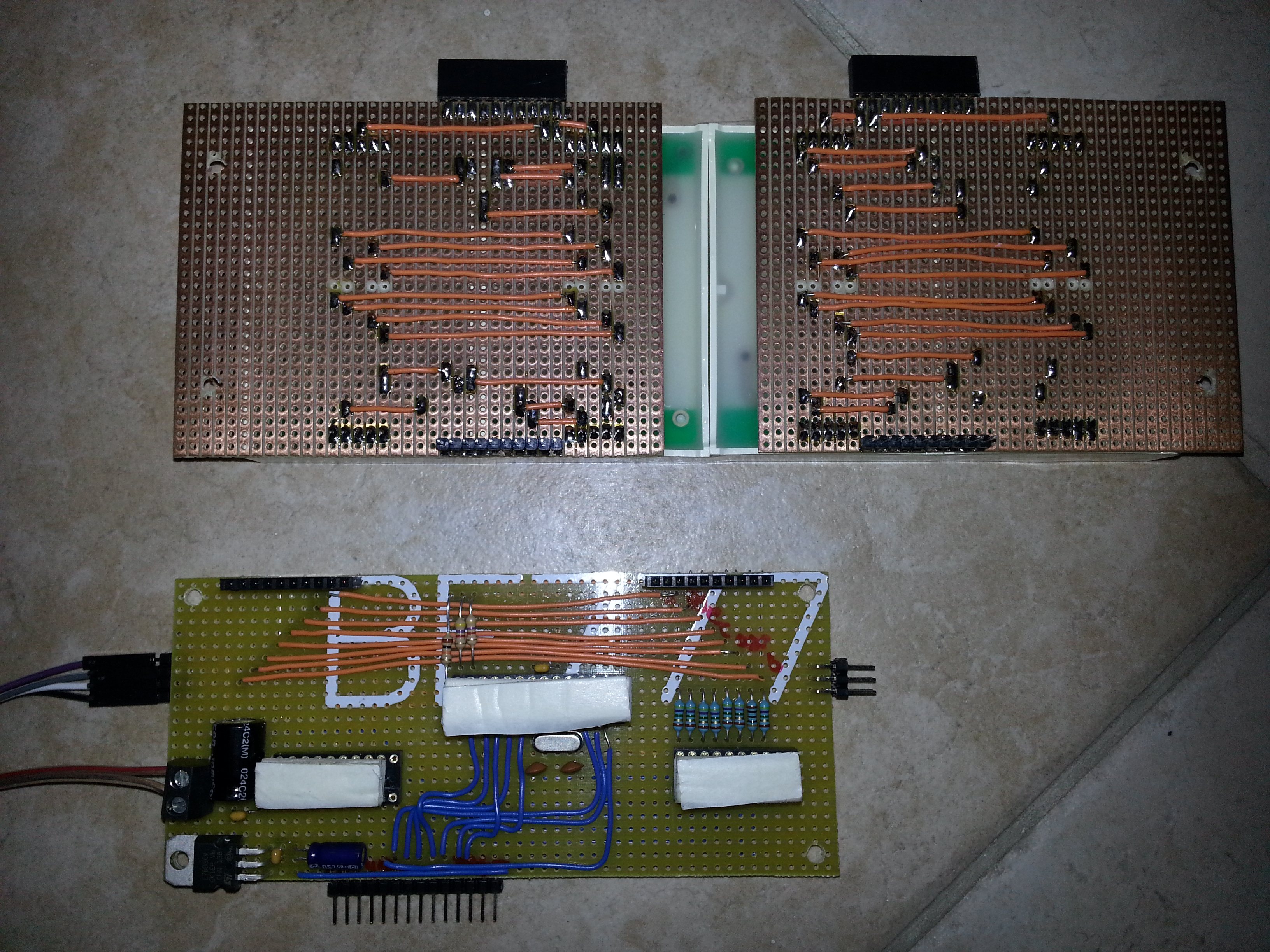
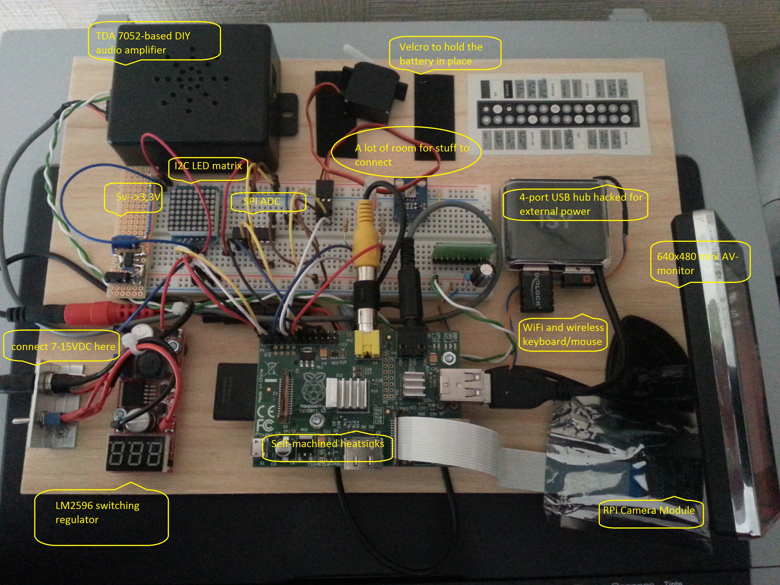
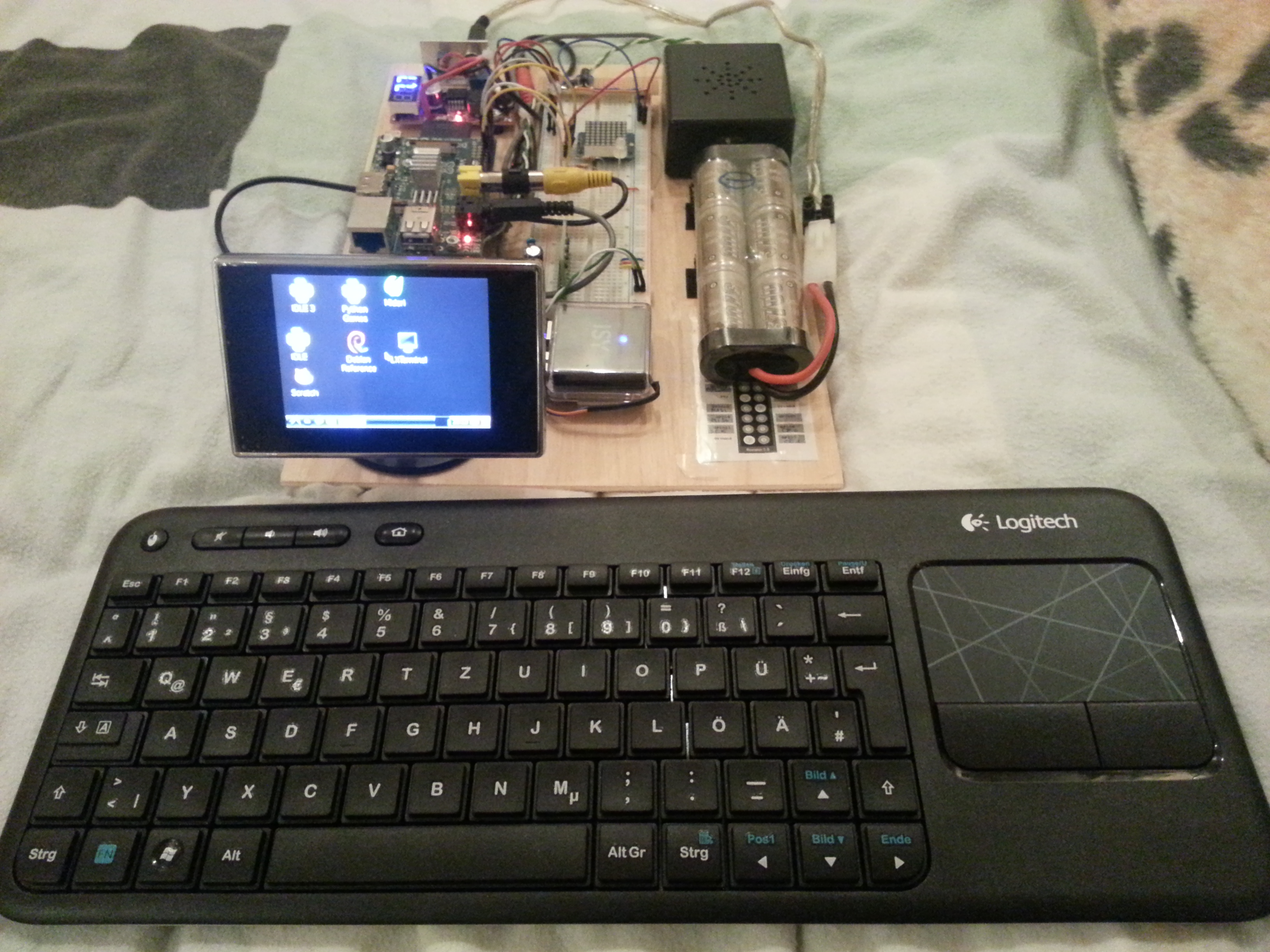
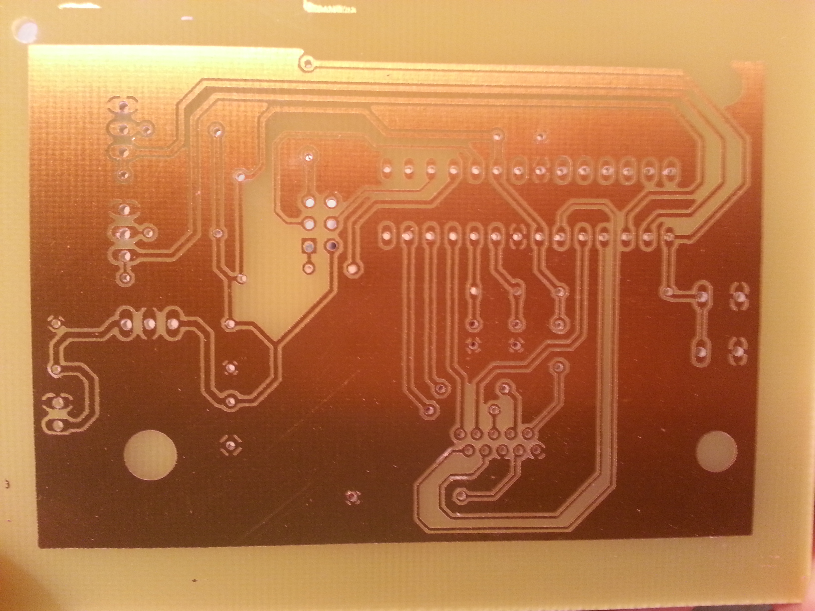
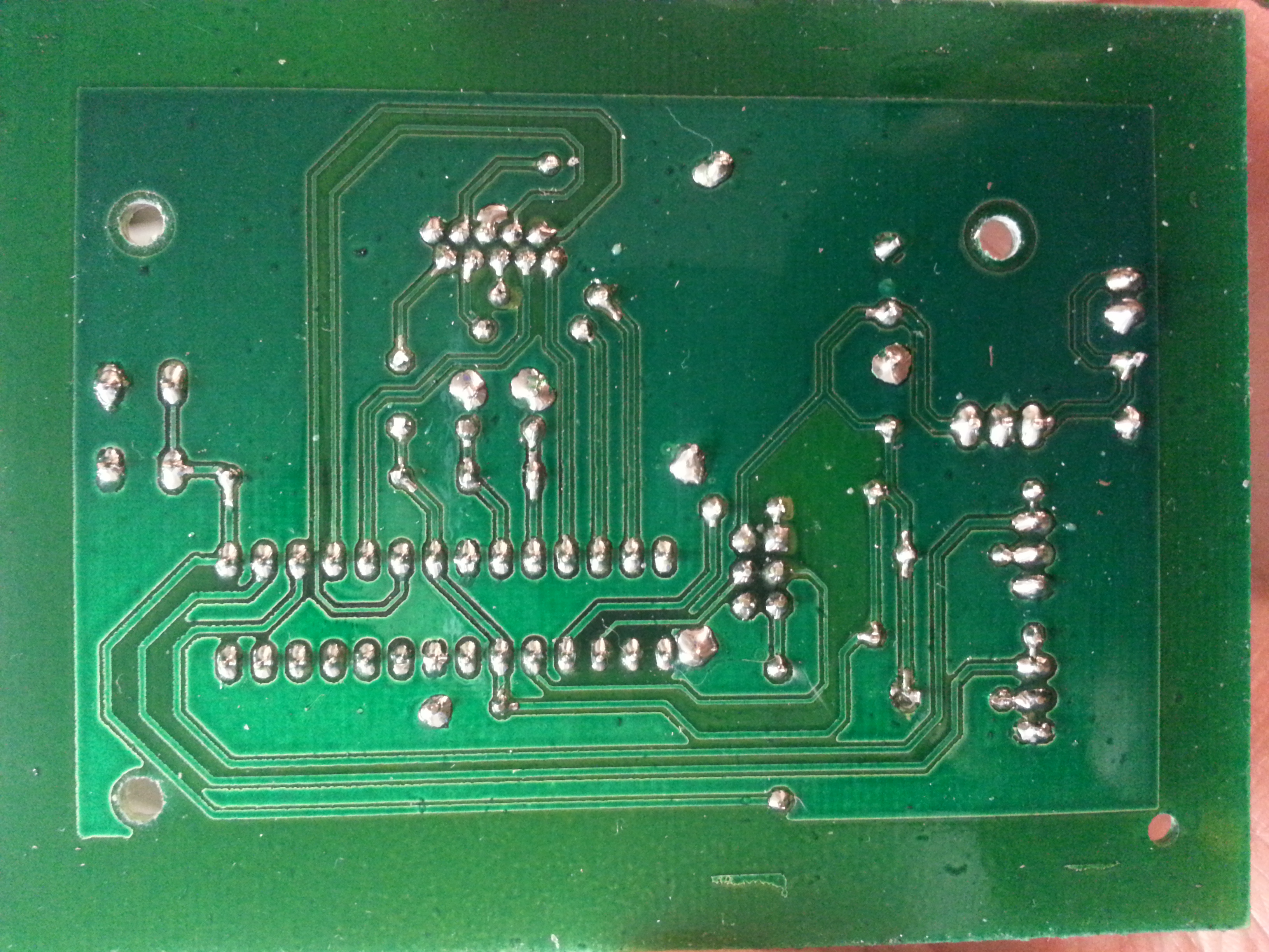
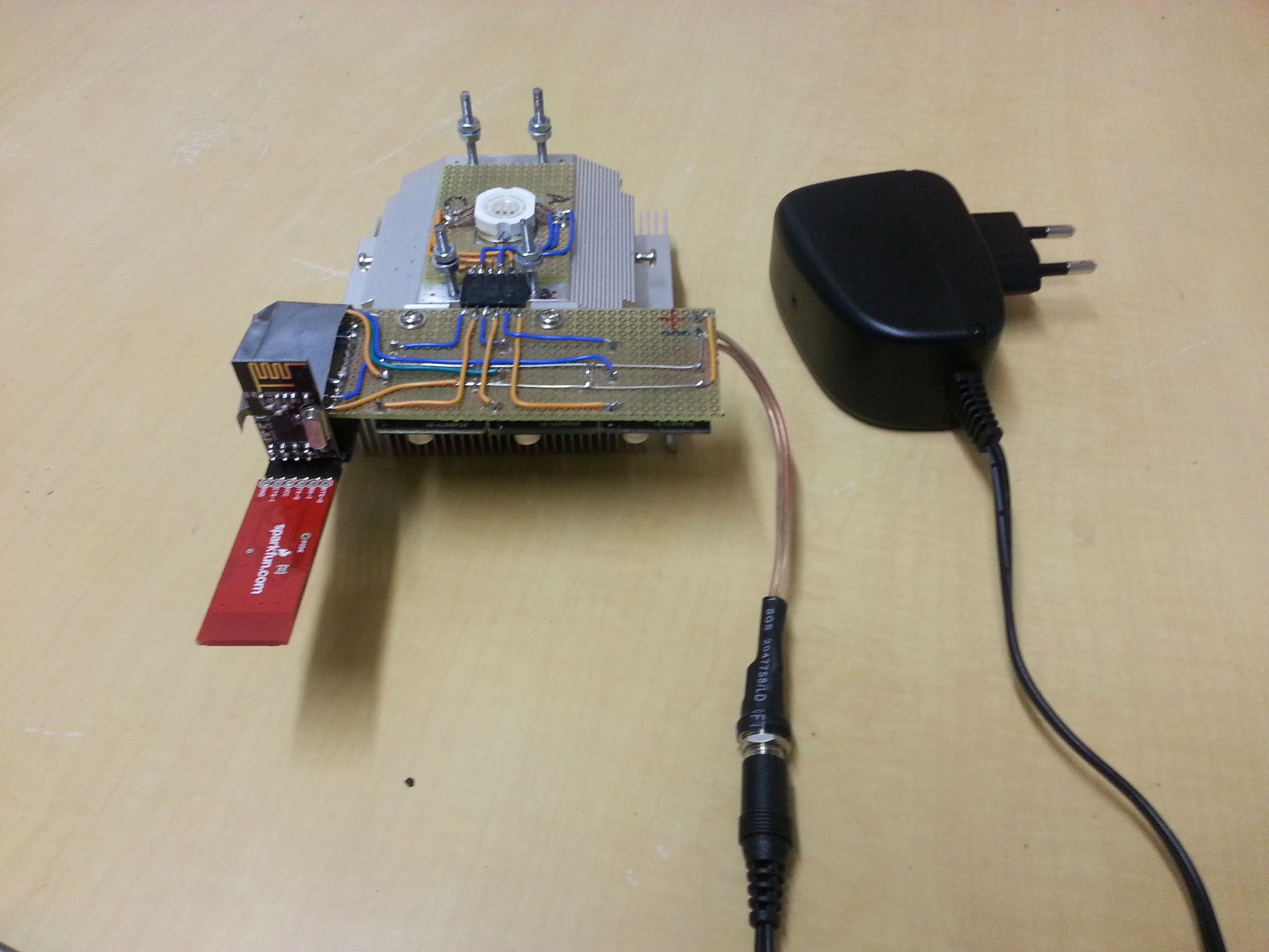
This little project just continues growing. All circuits are built on perfboards, mostly using discrete components. The Arduino components are really bearbones and make a great base for further development, as the basic functions such as movement and obstacle detection are already worky nicely.


I’ve added a “ceiling” on top, which is a blank perfboard for now. Anything can be mounted/soldered to it, for example a 2.4 GHz wireless camera with moving mechanics+electronics. For programming you have to connect an FTDI breakout board/cable.


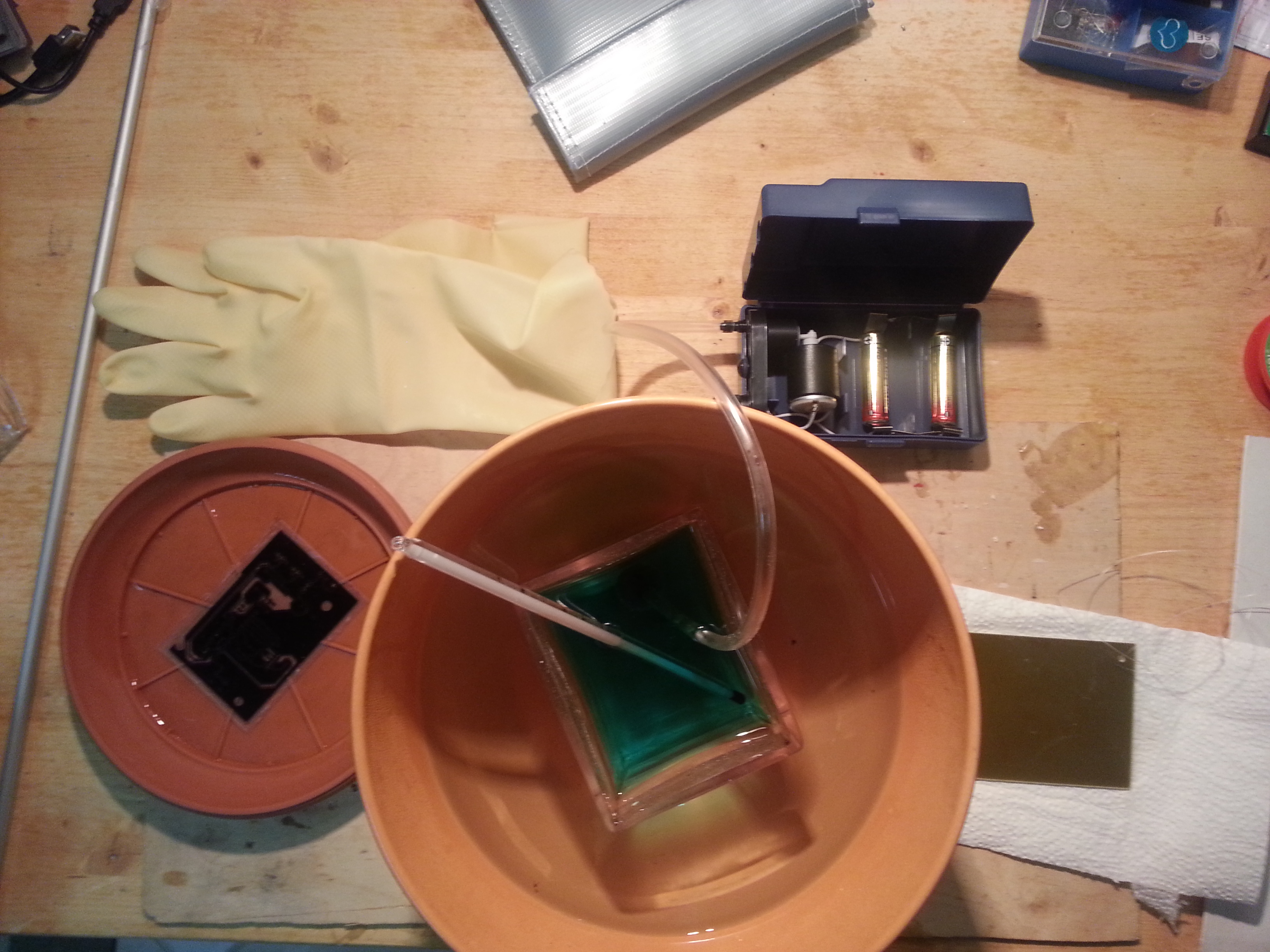
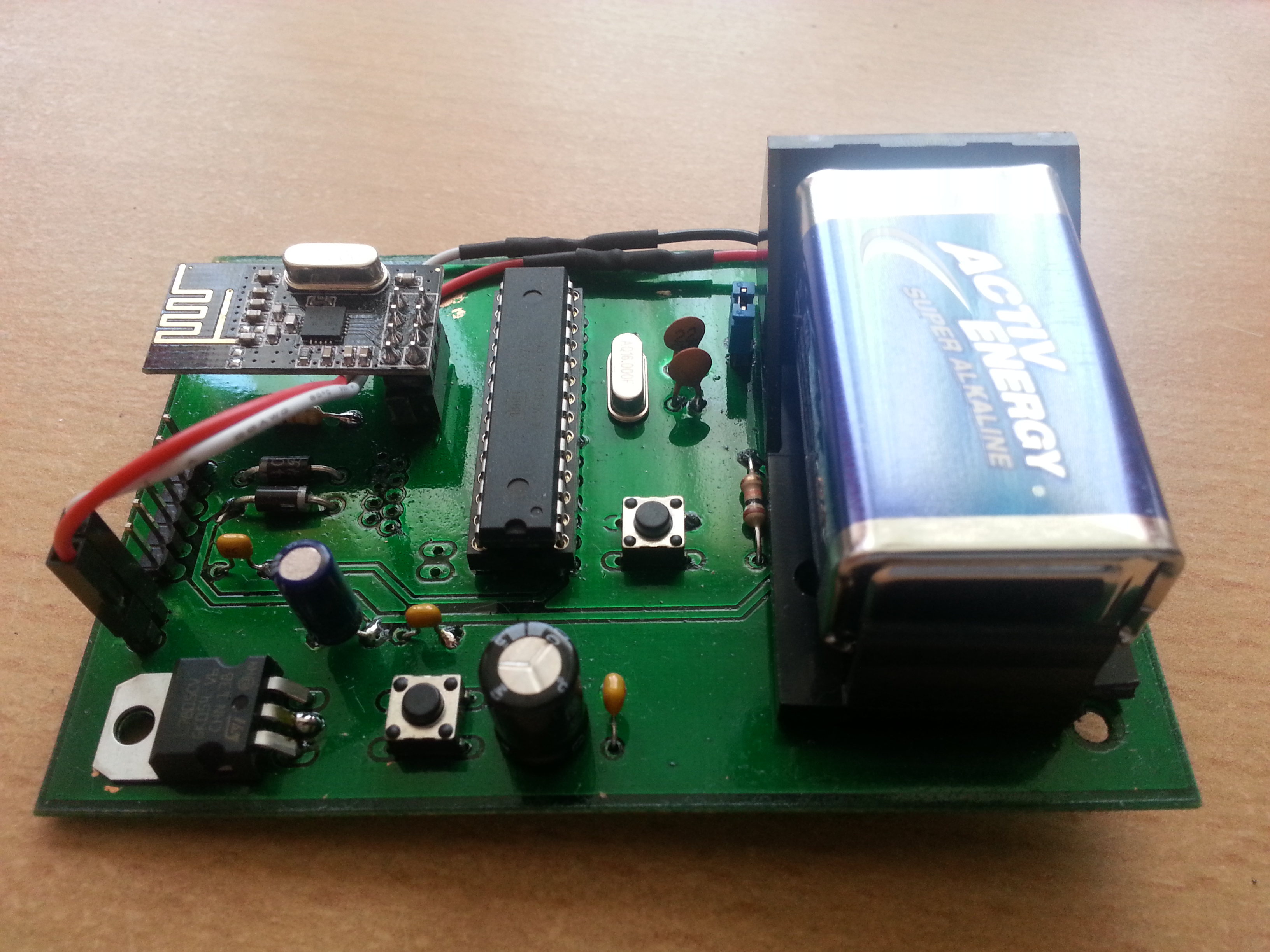
The H-Bridge is a quite simple design. Only 2 MCU pins are needed for speed control and reverse in direction. As for now, the device is working with 2 separate power supplies: 4 AA cells for the motors and a 9V battery for the “brain”/wireless camera. This is not really elegant, but it was the simplest way of eliminating the noise caused by the DC motors.


RelaisundFet


Here’s the dude in motion. Pretty fast and stable …


This is the stationary mode (if you just turn it on, but don’t send it any commands yet): it has got a character of its own 😉 It rotates for a random time period, which makes its behaviour quite unpredictable, yet wirelessly controllable with the current firmware.


The Arduino code and the corresponding Android app (created with the MIT App Inventor) can be found under the download link below. The app is somewhat universal, since it sends ASCII characters when a button is pressed, but its most useful feature is its bluetooth management functions, which supports pretty much all baud rates.


Tamya Robot


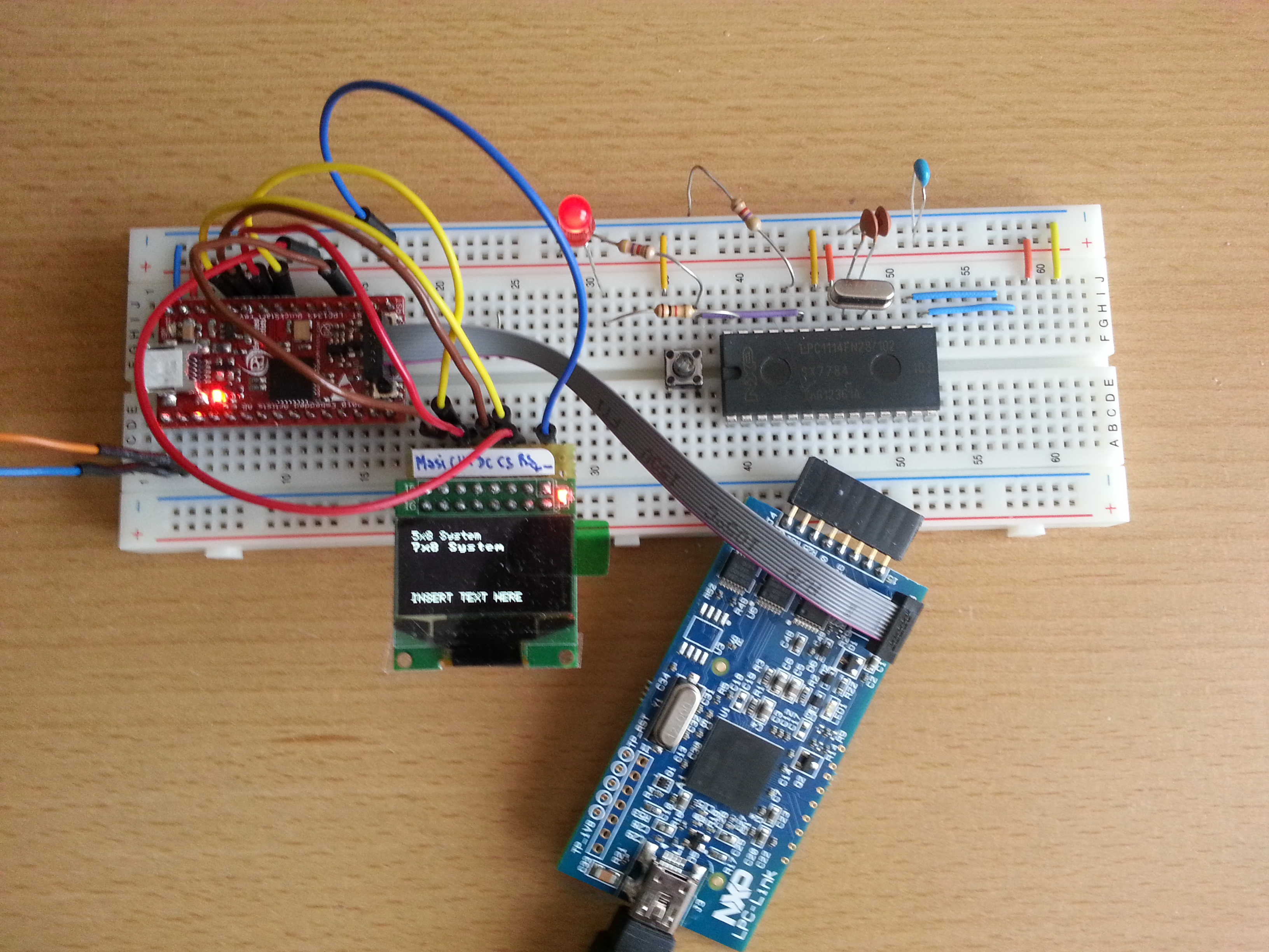
Another modification I’ve done on this robot is adding a thumb-joystick-controlled X-Bee-based remote control. Since this mod was only a temporary breadboard hack, I don’t remember the connection details but they were pretty simple and can be read out of the code.


Transmitter code:

//Robot controller TX part: analog joystick on A4 and A5
//Xbee module connected to TX and RX of the Arduino
int left_PWM, right_PWM, dir = 0;
int fb = 0;
int lr = 0;

void setup(){
  Serial.begin(57600);
}

void loop(){
  fb = analogRead(A4);
  lr = analogRead(A5);
  right_PWM = 0;
  left_PWM = 0;
  
if(fb > 530){      //back
    dir = 1;
    fb=map(fb,1023,530,255,0);
      
    if(lr < 480){
      lr = map(lr,480,0,0,255);
      left_PWM = fb - lr;
      right_PWM = fb;
      
    } else if(lr > 520){
      lr = map(lr,520,1023,0,255);
      
      left_PWM = fb;
      right_PWM = fb - lr;
    } else {
      left_PWM = fb;
      right_PWM = fb;
    }
}else if(fb < 490){    //forward
    dir=0;
    fb=map(fb,0,490,255,0); 
    
    if(lr < 480){
      lr = map(lr,480,0,0,255);
      left_PWM = fb - lr;
      right_PWM = fb;
    }else if(lr > 520){
      lr = map(lr,520,1023,0,255);
      left_PWM = fb ;
      right_PWM = fb- lr;
    }else{
      left_PWM = fb;
      right_PWM = fb;
    }
} else if(lr < 480){    //only left track activated 
    lr = map(lr,480,0,0,255);
    left_PWM = 0;
    right_PWM = lr;
    dir = 0;
 }else if(lr > 520){    //only right track activated
    lr = map(lr,520,1023,0,255);
    left_PWM = lr ;
    right_PWM = 0;
    dir = 0;
  }else {
    left_PWM = 0;
    right_PWM = 0;
    dir = 0;
}

//create string and send
String dataString = String(dir);
dataString += ',';
dataString += left_PWM;
dataString += ',';
dataString += right_PWM;
dataString += '\n';
Serial.print(dataString);

//delay to recover
delay(100);
}


Robot code:

//Robot Thumb Joystick Remote Control Sketch
//X-Bee module connected to TX and RX of the Atmega328
//Vehicle code: receives the strings via serial from the Xbee module and controls the 
//power mosfets on left/right c_pins via PWM to drive the tracks

const int sensorPin = A0;       // SHARP Sensor

const int left_dir_pin = 4;     // all the motor pins
const int left_c_pin = 5;
const int right_dir_pin = 7;
const int right_c_pin = 6;

const int led = 13;              //green LED on SCK (digital pin 13)

int sensorValue = 0;    // variable to store the value coming from the sensor

unsigned int sensor_threshold = 200;
String inString = "";    // string to hold input
int currentNumber = 0;  //counter for value indices
int dir, left_PWM, right_PWM = 0;  //values read from the received String
//---------------------------------------------------------------------------
void setup() 
{
  // declare the motor pins and led-pin as an OUTPUT:
  pinMode(left_dir_pin, OUTPUT);
  pinMode(left_c_pin, OUTPUT);
  pinMode(right_dir_pin, OUTPUT);
  pinMode(right_c_pin, OUTPUT);
  pinMode(led, OUTPUT);
  //zigbee-modem-baud rate
  Serial.begin(57600);
}
//----------------------------------------------------------------------------
void loop() 
{
   int inChar;
  
  // Read serial input:
  if (Serial.available() > 0) {
    inChar = Serial.read();
  }

  if (isDigit(inChar)) {
    // convert the incoming byte to a char 
    // and add it to the string:
    inString += (char)inChar; 
  }

  // if you get a comma, convert to a number,
  // set the appropriate value, and increment
  // the counter:
  if (inChar == ',') {
    // do something different for each value of currentNumber:
    switch (currentNumber) {
    case 0:    // 0 = direction 
      dir = inString.toInt();
      // clear the string for new input:
      inString = ""; 
      break;
    case 1:    // 1 = left:
      left_PWM = inString.toInt();
      // clear the string for new input:
      inString = ""; 
      break;
    }
    currentNumber++;
  }
  if (inChar == '\n') {
    right_PWM = inString.toInt();

  digitalWrite(left_dir_pin, dir);  //if 0, tank goes forward
  digitalWrite(right_dir_pin, dir);
  analogWrite(left_c_pin, left_PWM);   //PWM 
  analogWrite(right_c_pin, right_PWM);
  // clear the string for new input:
    inString = ""; 
    // reset the color counter:
    currentNumber = 0;
  }

}


Color-Sensing RGB Light

…using nrf24l01 radios and the tcs3200 color sensor.


A word of warning: a chameleon does NOT change its color depending on the surface it is situated on, but depending on mood and temperature! This lamp does change its color depending on the color you show it. So we’re trying not to call it chameleon lamp.


This upgrade of a former project uses nrf24l01 spi-controlled cheap 2.4GHz radio modules for communication of the 10W RGB LED lamp built around an Arduino Pro Mini and three MBI6651 PWM-dimmable LED drivers.


The remote control uses a TCS3200 color sensor that uses rate coding to tell the microprocessor which color it senses. It is then packaged as a RGB string and sent to the lamp. For example pure red @ full brightness would be 255,0,0; The processor in the remote control is also an Atmega328p programmed in the Arduino IDE.


20131015_201445


This project was another opportunity to create a DIY PCB. This time I took it to the next level and made it double-sided. A laser printer and laser transparencies were used, which is also an upgrade to inkjet stencils. I applied some toner density spray to the transparencies prior to exposing and hoped for better exposure results. It seemed to improve outcome. Of course the good old solder coat was sprayed onto both sides after etching.


Note: the extra holes are for the ribbon cable connector for a Pollin 2×8 character LCD. I haven’t soldered it.


The color sensor board is attached face-down and therefore needs a window in the PCB. Made that using a PROXXON mill.


chameleon tx top


The result was a good homemade PCB. The other extra holes are for a 7805 voltage regulator and a power pushbutton. Since the nrf modules are pretty solid and connect to each other immediately, you can just disconnect the transmitter from its power supply and the light remembers the color you showed it.


The device remains controllable via bluetooth UART (for example via Android applications).


chameleon tx bottom


After testing I found out that the headers were too high for the sensor to properly detect surfaces and so I had to solder the TCS3200 PCB to the main PCB in a weird fashion in order to allow closer sample positioning to the sensor. Below the final version is shown with a 9V battery attached directly to the PCB.


20140606_161744


20140606_161818


Arduino code for the transmitter and receiver:


ChameleonRGBlamp


Eagle files for the transmitter (include schematics):


ChameleonTX
dammit, called it chameleon again.


Android App code for Android SDK based on basic bluetooth socket code found online:


RGBlampRemote